Sonoff NSPanel EU Switch in Detail

Summary
Sonoff NSPanel teardown and detailed overview.
Full disclosure: This is a pre production unit sent to me free of charge by Sonoff. Some aspects of it might be changed once it reaches production. Review is not influenced by that fact and is solely my opinion. Shopping links in this article are affiliate links and I earn a small commission when you buy through them
Sonoff NSPanel is available through Itead store.
Time to dig in deeper into the new NSPanel and see what possibilities it hides inside.
Relay Unit
Remove the touch plate from the relay unit by unclipping it. Pop the plastic cover over the relay housing.
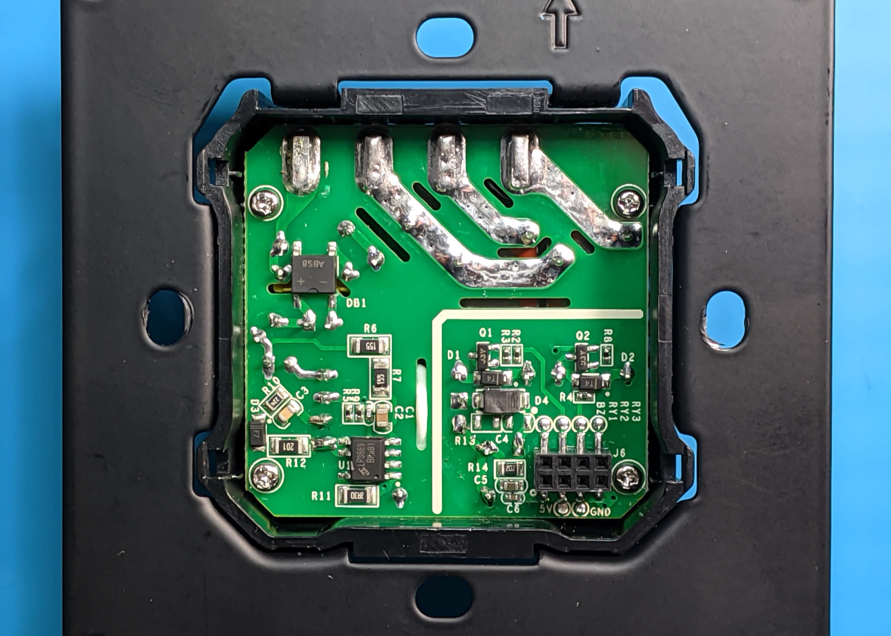
You can notice that the headers are labelled BZ, RY1, RY2 and RY3. RY1 and RY2 are the existing relays and logic dictates RY3 is for the third relay. Either a plan for the future or it got removed during design. BZ is most likely a buzzer which also is not present on the PCB and I didn’t notice a spot for it.
To get the PCB out of the housing remove the 4 screws on top and the 4 screws in the wire terminals. Now you can push it out from the back.
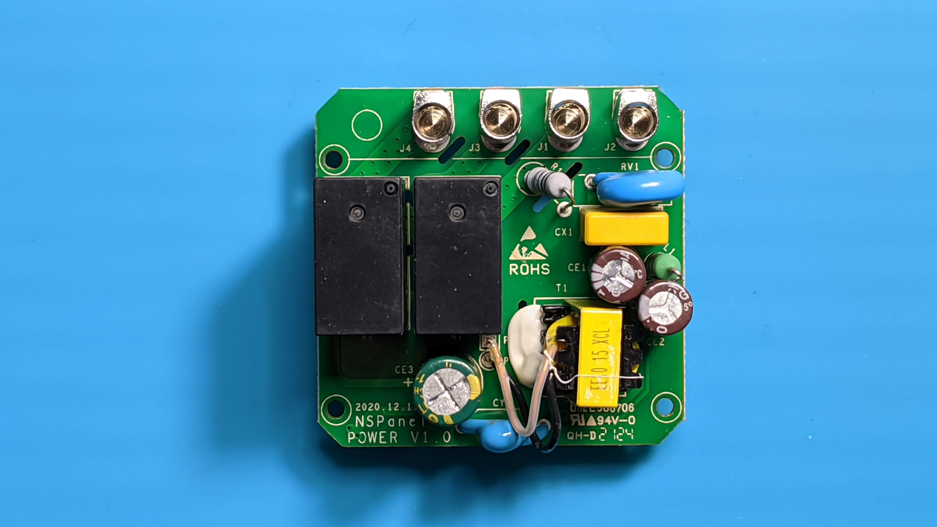
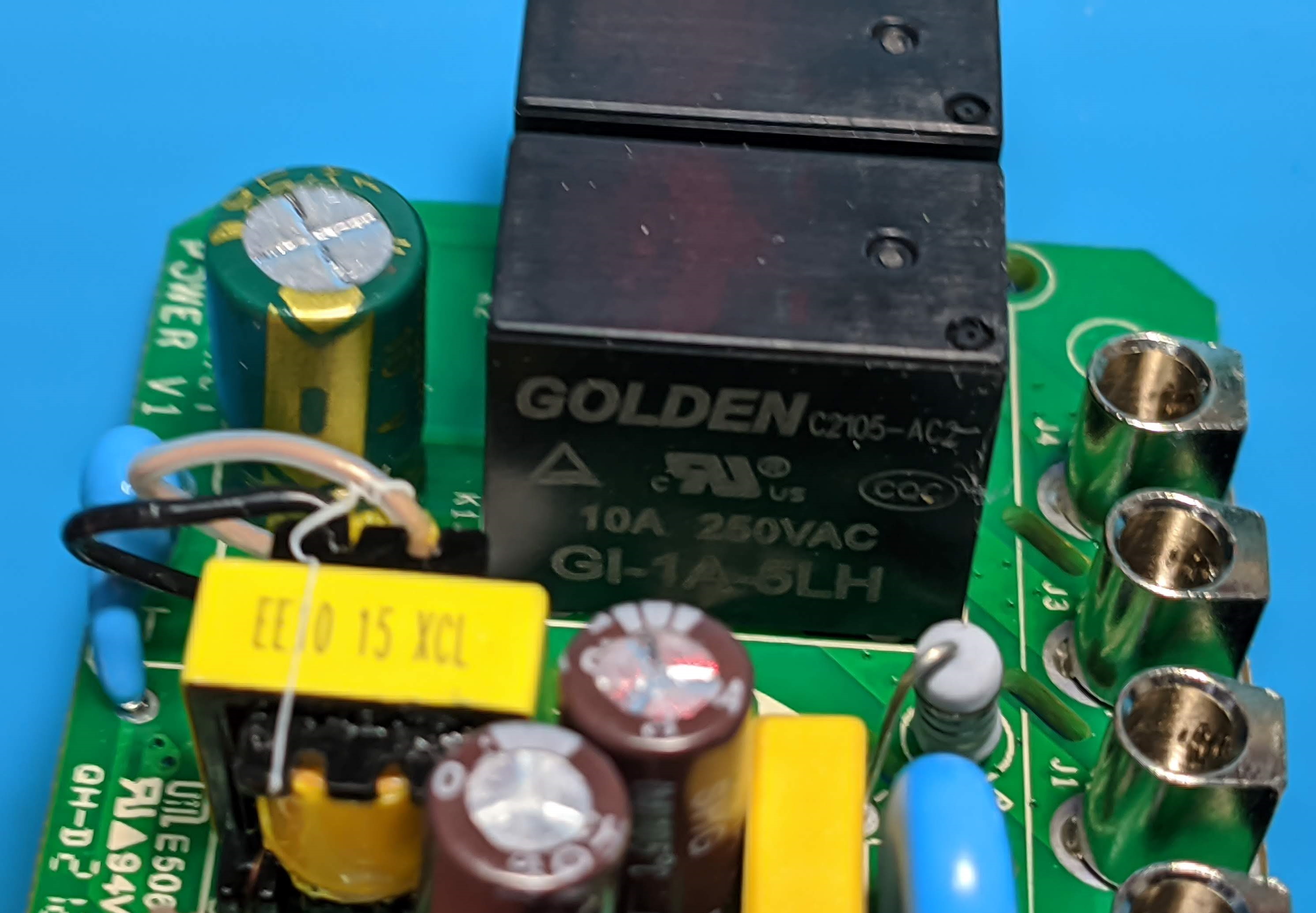
As you can see, the relays are rated for 10A so the 2A per relay official switch rating must be caused by the PCB design. I cannot reliably guess why exactly, it could be the mains solder traces or possible overheating concerns or who knows…
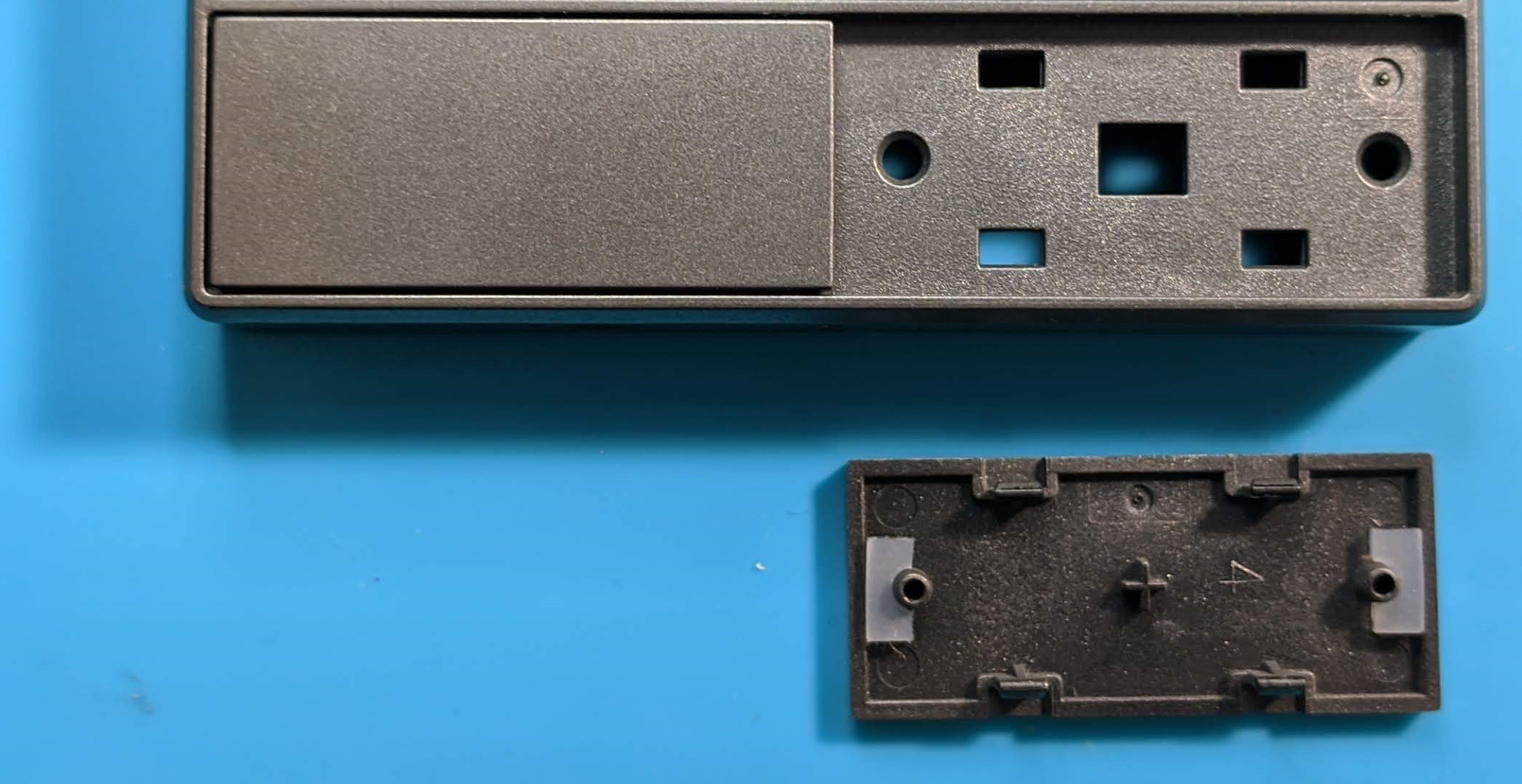
Touch Plate
Touch plate has only two screws holding the plastic cover. Removing it reveals a well labeled PCB marked “E32-MSW-NX” and “NSPanel-EU”.
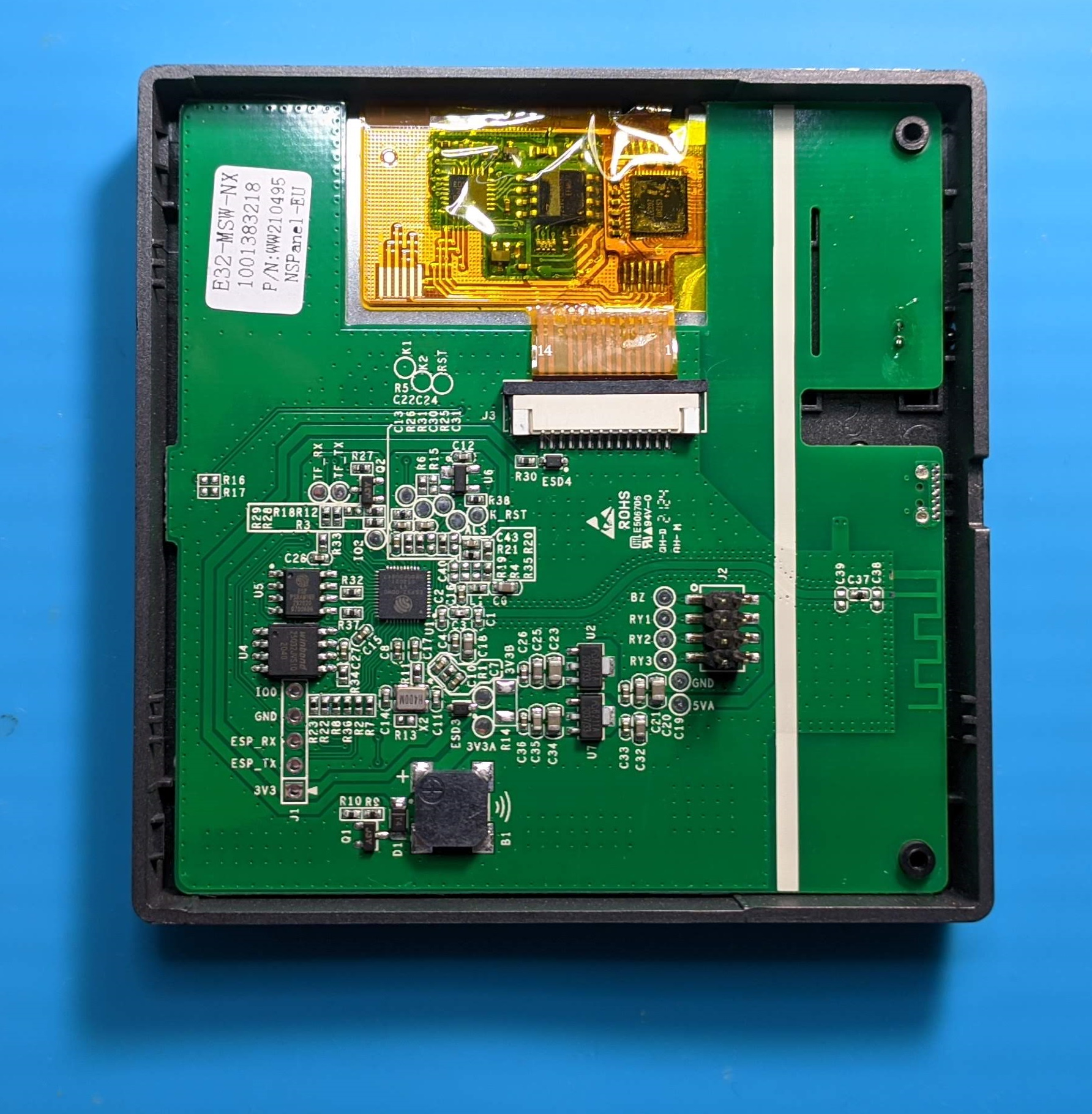
Eyes immediately jump to the bottom 5 pin holes that we all love to see: 3V3, RX, TX, GND and IO0. Easy access for flashing! If you solder permanent headers there make sure to protect the other side with electrical tape to prevent shorting them out on the metal screen shield.
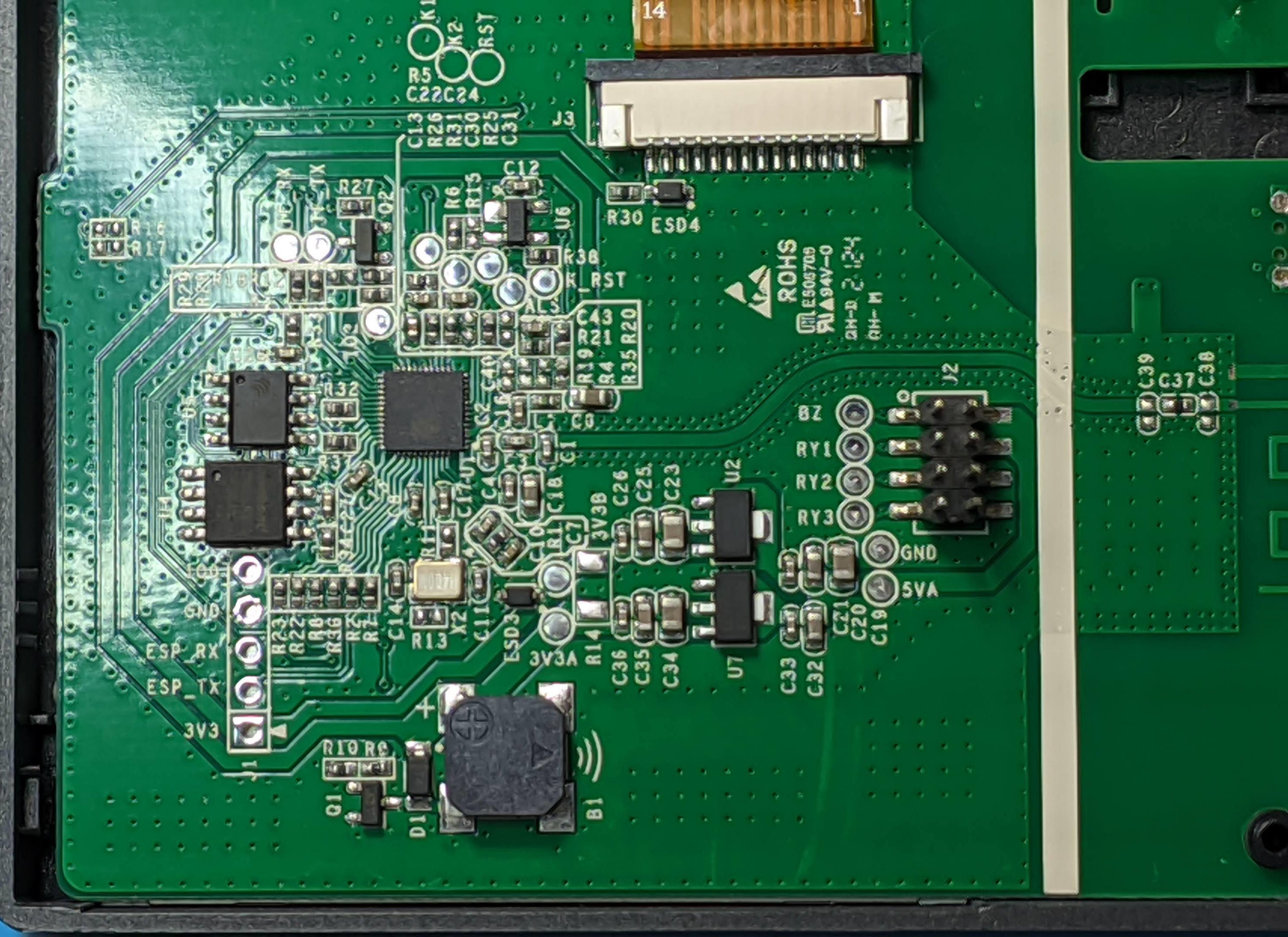
Above the headers is the cluster with the ESP32. The brain is an ESP32-D0WD-V3 chip complemented with 4MB Winbond flash and a 16MB PSRAM chip. On the right side is the header that connects to the relay unit with the same labelling and test pads.
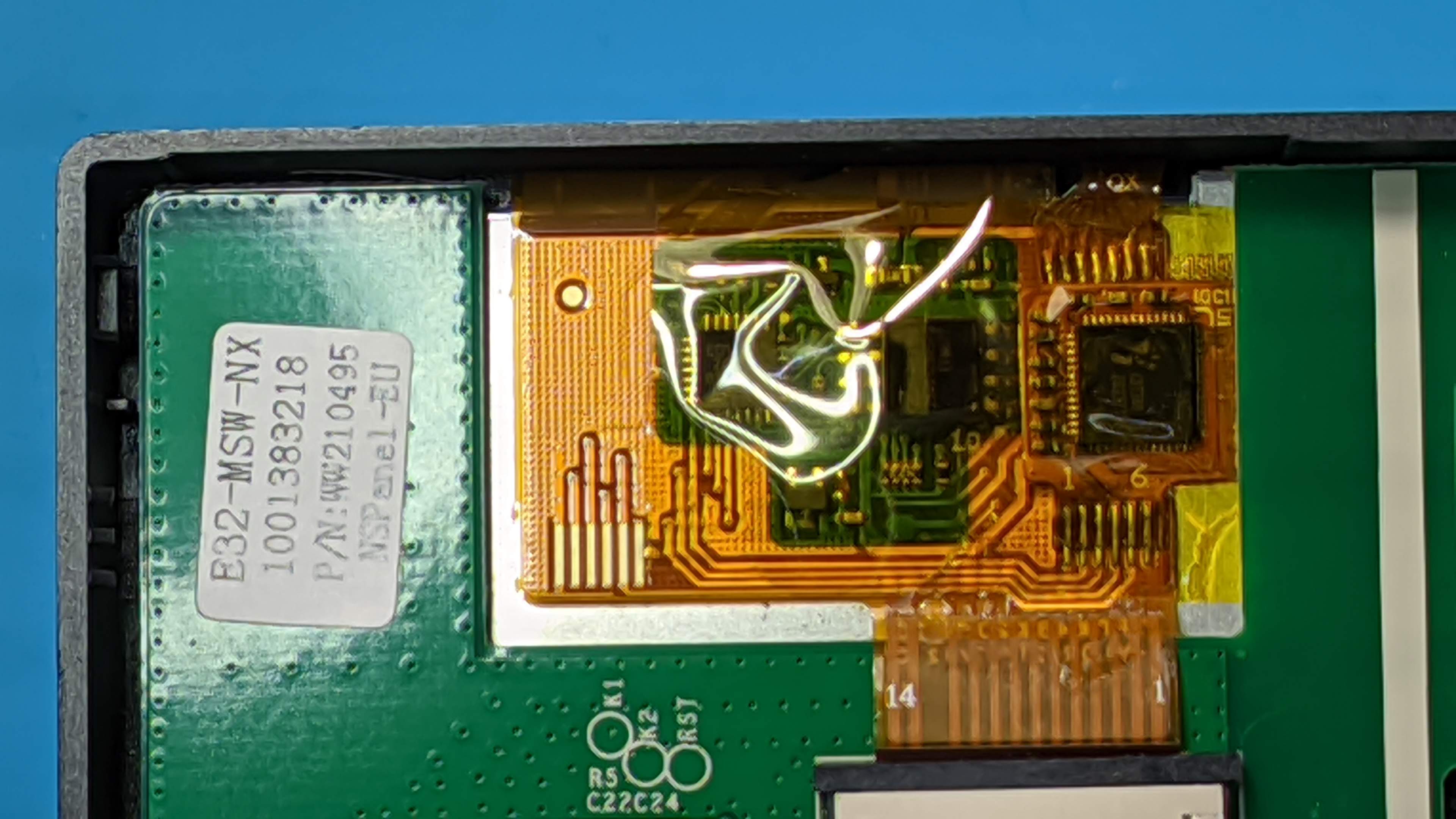
At the top, nestled under Kapton tape is the Nextion screen controller and touch MCU. Nextion screens use ARM chips as a controller and this one uses STM32G031G8. CST340 is the touch controller for which there’s very little information on the internet.
What’s interesting about Nextion screens is that they do not need a microcontroller to draw each pixel but instead it stores the entire GUI in its controller and uses serial communication with the ESP32 to send and receive events. To see what exactly is going on between the two Sonoff kindly left the TF_RX and TF_TX pads to make our lives easier, but even if they were not there there is ample access at the screen connector.
To remove the PCB you have to disconnect the screen. Push the black bar on both sides until it looses its grip on the flat cable then carefully pull it out.
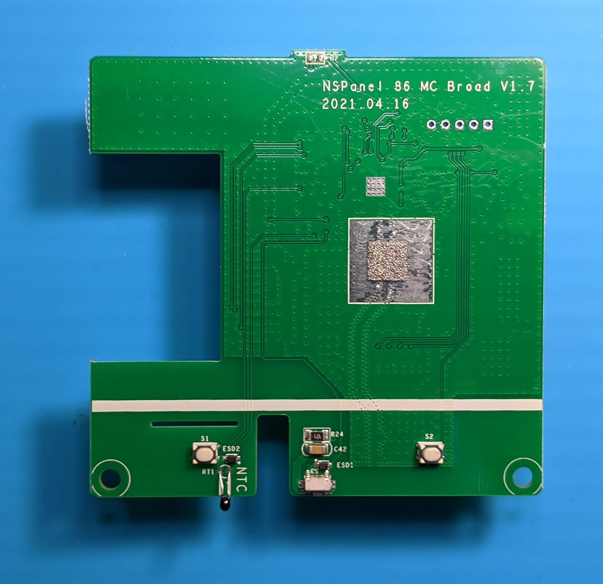
The other side of the PCB reveals another moniker for the switch: “NSPanel 86 MC Broad V1.7”. I guess at least one typo is obligatory! It will be interesting to follow the iterations of the design and I wonder which version had all 3 relays and a buzzer.
A peculiar detail is the unpopulated spot at the top labelled “H2”. I have my suspicions that it was supposed to be a humidity sensor, partly because of the H and partly because the firmware reports a static humidity value of 50 together with the temperature. Another case of an abandoned feature or a sign of things to come?
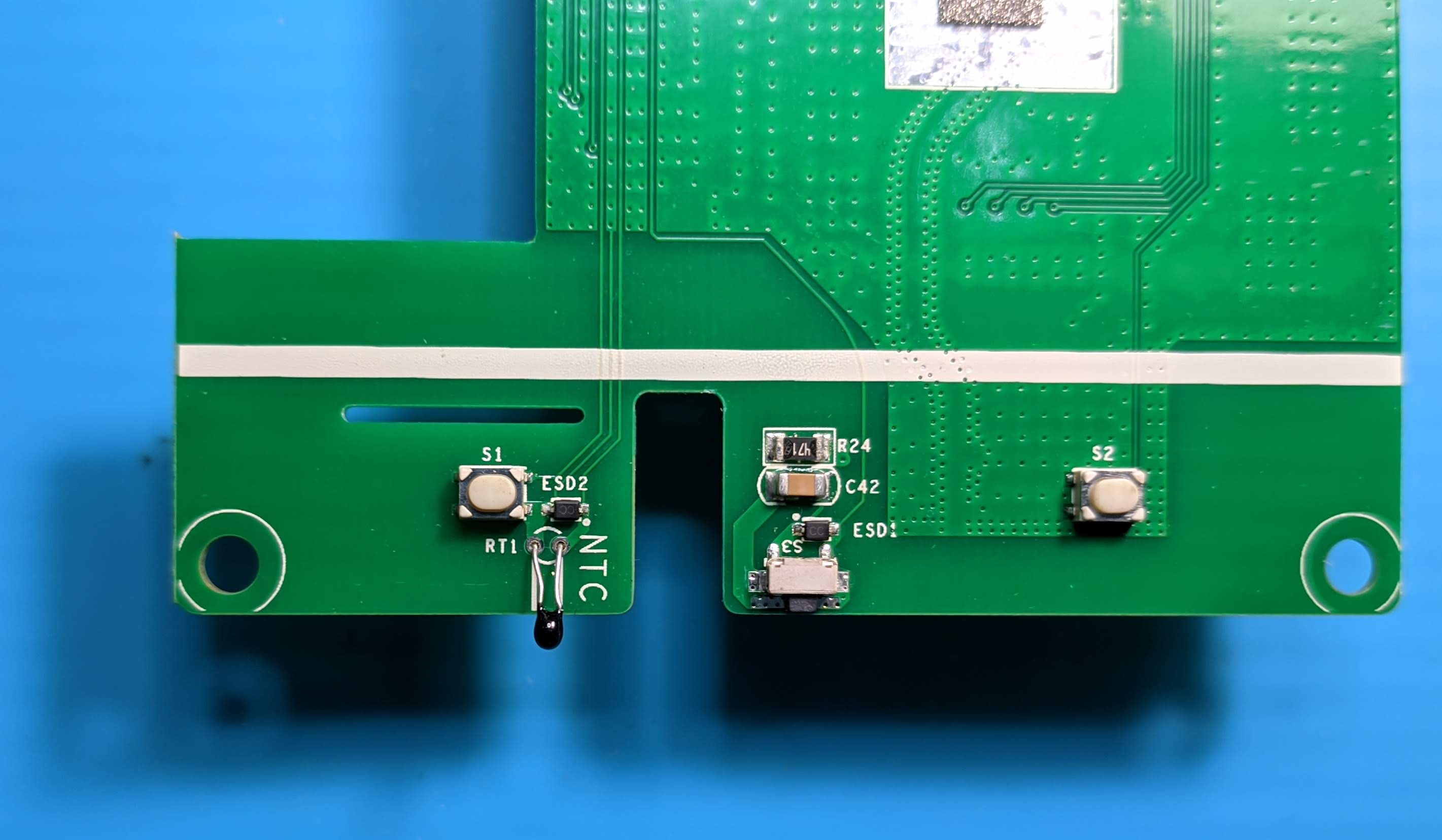
That little black drop labelled NTC is the temperature sensor. Sonoff confirmed it is an NTC thermistor probe model MF52A R = 10K±1% B = 3950K±1%.
Exactly in the middle is the reset button reachable through the pin hole in the switch housing.
At the bottom are the two buttons used for switching. Now I understand why they were so bad to press with lousy feedback. The plastic switches have only the two white rubbery pieces instead of a real spring which just contributes more to the mushy feel and the false feedback without actually actuating the buttons when pressed at the edges.
I would’ve preferred some nice, clicky Omron microswitches and a rocker keys with a spring. Hell, just a simple capacitive touch would be better… Hmmmm, now that’s an idea.
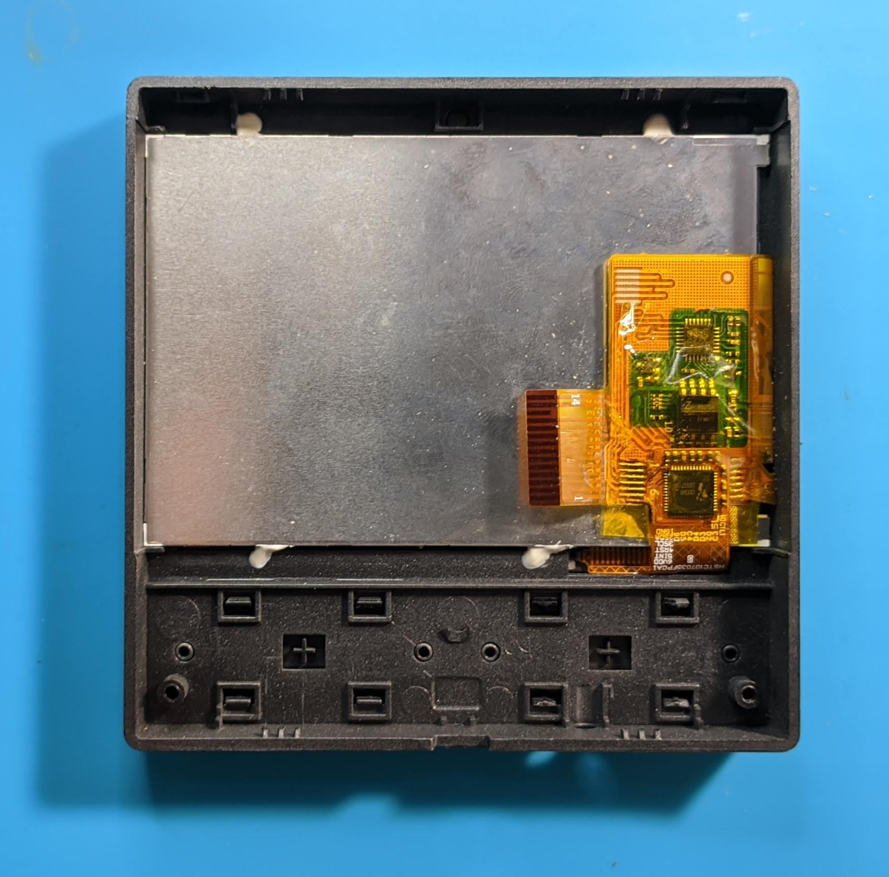
The screen is glued to the front panel heavily and encased in the metal shielding I mentioned before.
EDIT:
I’ve managed to get the Nextion screen type after issuing the upload protocol sequence.
comok 2,30614-0,NX4832F035_011C,48,61744,16643401829EF850,16777216ÿÿÿ
This means its a Nextion Discovery 3.5” NX4832F035 (Datasheet) but with a capacitive touch panel.
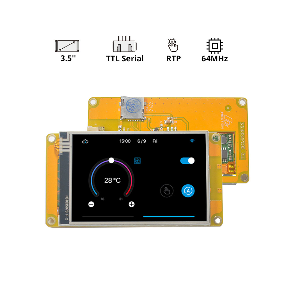
With this discovery we confirm it is possible to upload custom GUI created in Nextion Editor.
Pinout
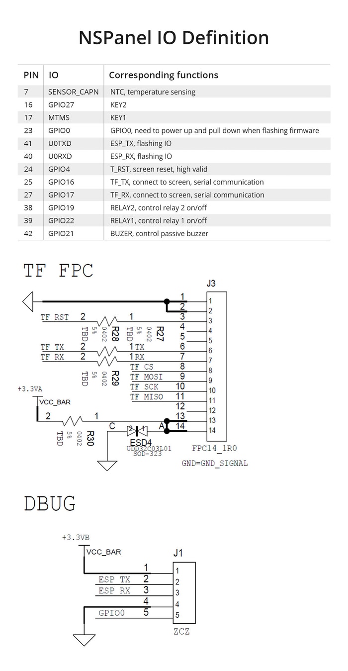
I’ve had some quality time with my tiny multimeter and noted down the pinouts.
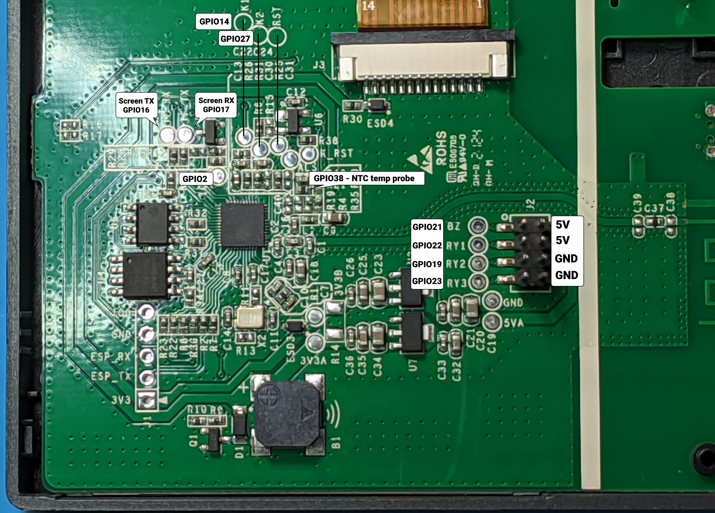
- U0RXD - ESP_RX
- U0TXD - ESP_TX
- GPIO17 - TF_RX
- GPIO16 - TF_TX
- GPIO05 - PSRAM SCLK
- GPIO18 - PSRAM /CE
- GPIO09 - PSRAM SIO[3]
- GPIO14 - K1
- GPIO27 - K2
- GPIO37 - ALS
- GPIO04 - T_RST (screen reset)
- GPIO38 - NTC via R21
- GPIO02 - IO2
- GPIO21 - BZ
- GPIO22 - RY1
- GPIO19 - RY2
- GPIO23 - RY3
UPDATE: Sonoff officially released the pinout on the Kickstarter page and information about the Nextion upload protocol

Explore more like this
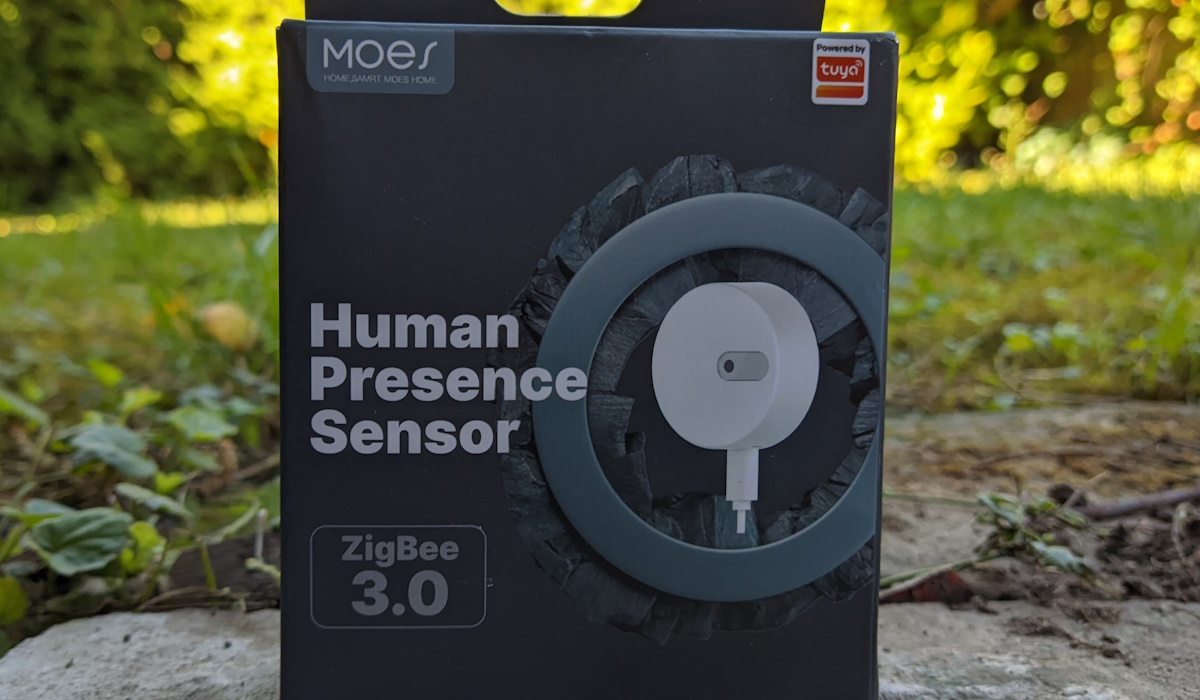
Moes ES1 (ZSS-LP-HP02) Zigbee Human Presence Sensor Review
It was hard to resist the new Moes labelled sensor on AliExpress because it looked identical to the Linptech ES1 sensor which works with Xiaomi’s Mijia ecosystem but I avoided...
Comments