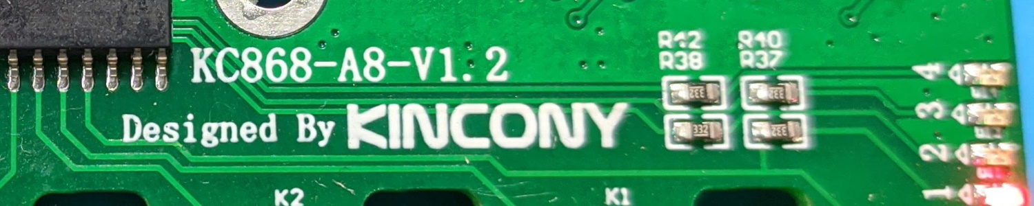
Kincony KC868-A8 ESP32 8 Channel Relay Ethernet Board with Tasmota
Summary
When you’re very serious about your home automation you go wired!
Full disclosure: This is a sample sent to me free of charge by Kincony. Review is not influenced by that fact and is solely my opinion. Shopping links in this article can be affiliate links from which I earn a commission at no additional cost to you
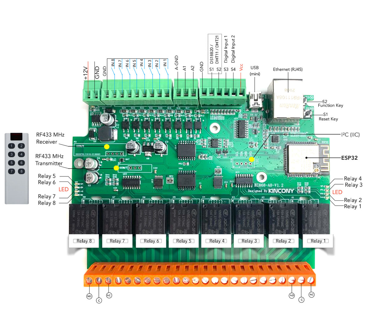
Remember Kincony KC868-A4? How about you double the relays and inputs and add Ethernet on top! Now with 8 relays and 8 inputs, possible using PCF8574. Besides that you still have RF send and receive, 2 analog inputs, 4 digital inputs usable for all kinds of sensors or even addressable LED strips and an extra 4 pin I2C header for even more expansion. As a cherry on top there’s an Ethernet port to make the communication all the more secure by going wired. All that in the same form factor and still controlled by ESP32 so you can even do Bluetooth. Board is powered by 12V DC.
It is available from Kincony AliExpress store in a couple bundle options.
Features
Kincony is still not giving up that mini USB, eh? Luckily I had the cable at the ready from reviewing the KC868-A4.
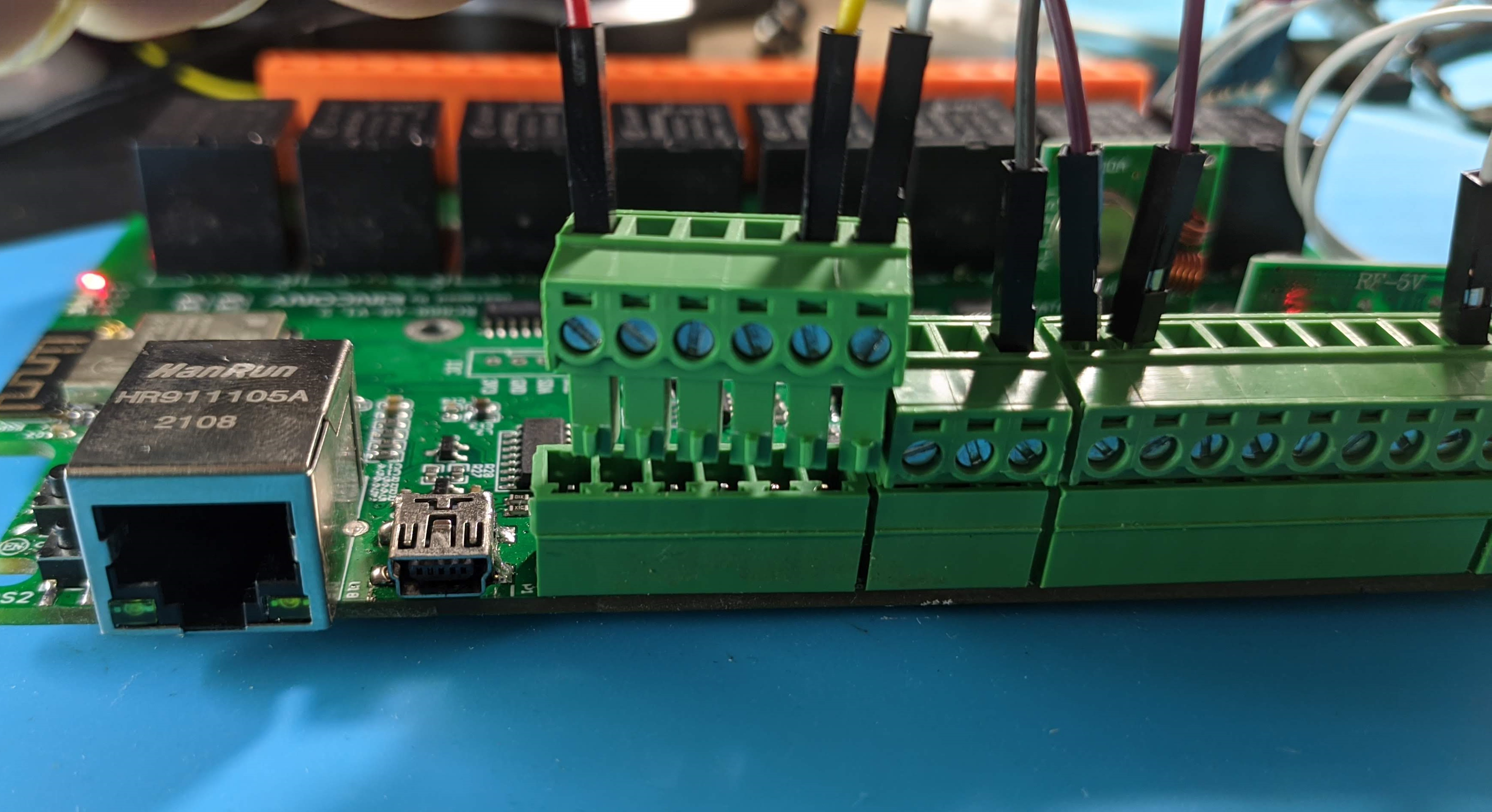
To power the board use the top left terminals labelled P6. I am happy to see the pluggable terminals again. I still love them. On a down note, there are no clear labels on the pin polarity so you have to consult the documentation this time.
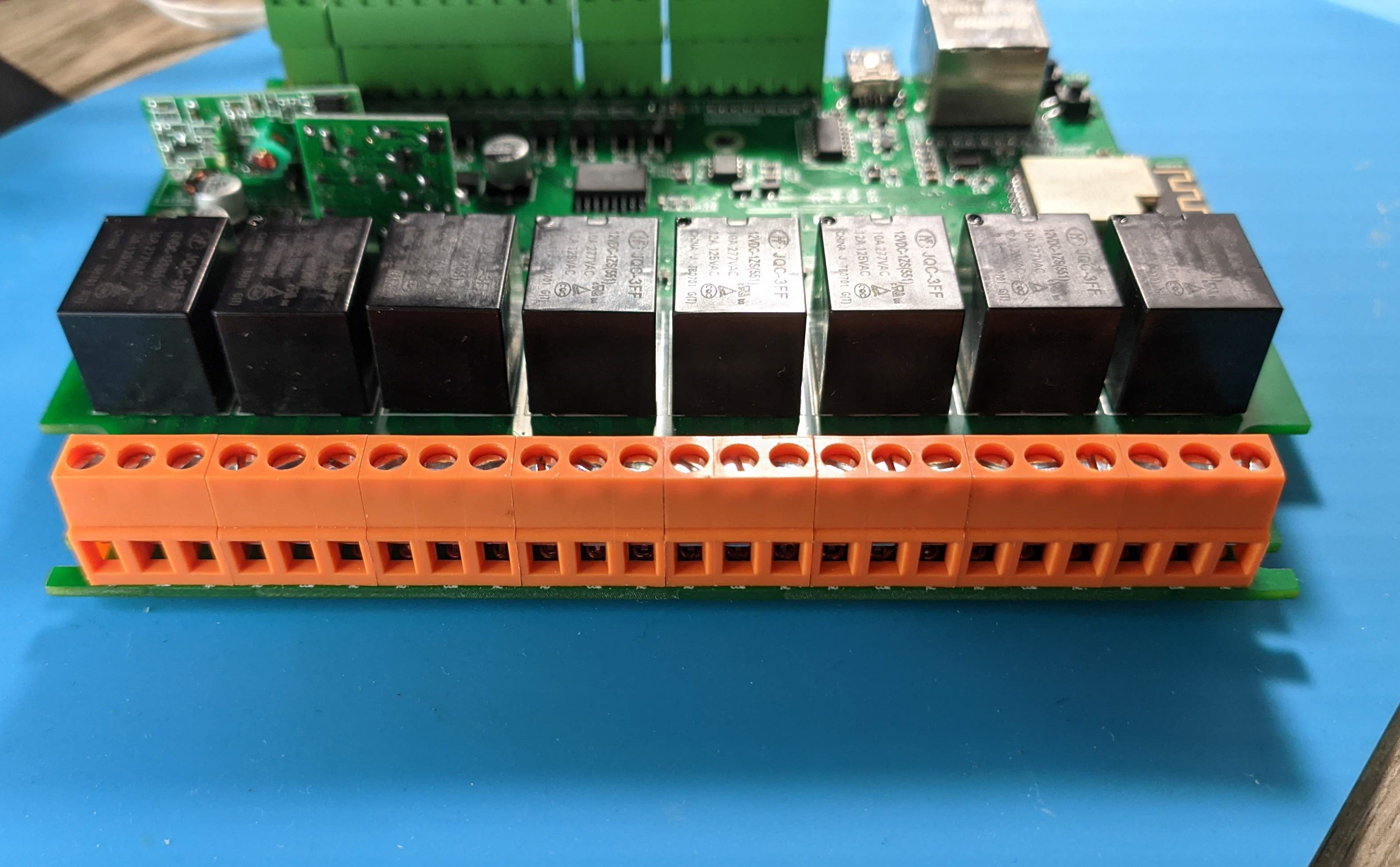
The 8 relay terminals are colored orange and have connections for both normally open and normally closed configuration. They’re rated up to 10A/277VAC or 12A/125VAC.
Next to the ESP32 module are the unpopulated headers to connect additional I2C devices complete with GND and power pins. Nice expansion option that was lacking from the A4 board.
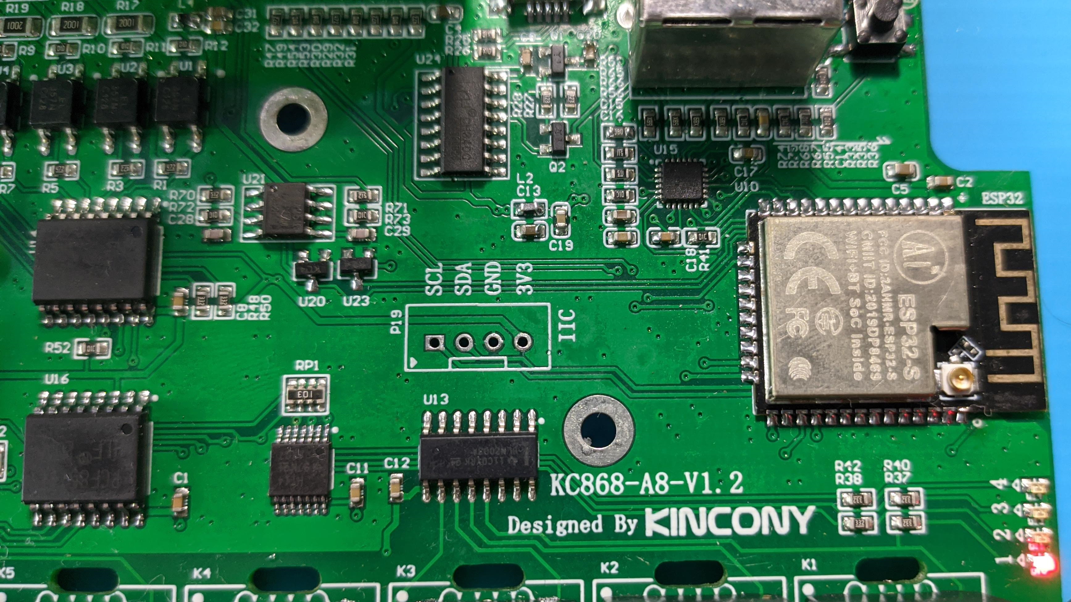
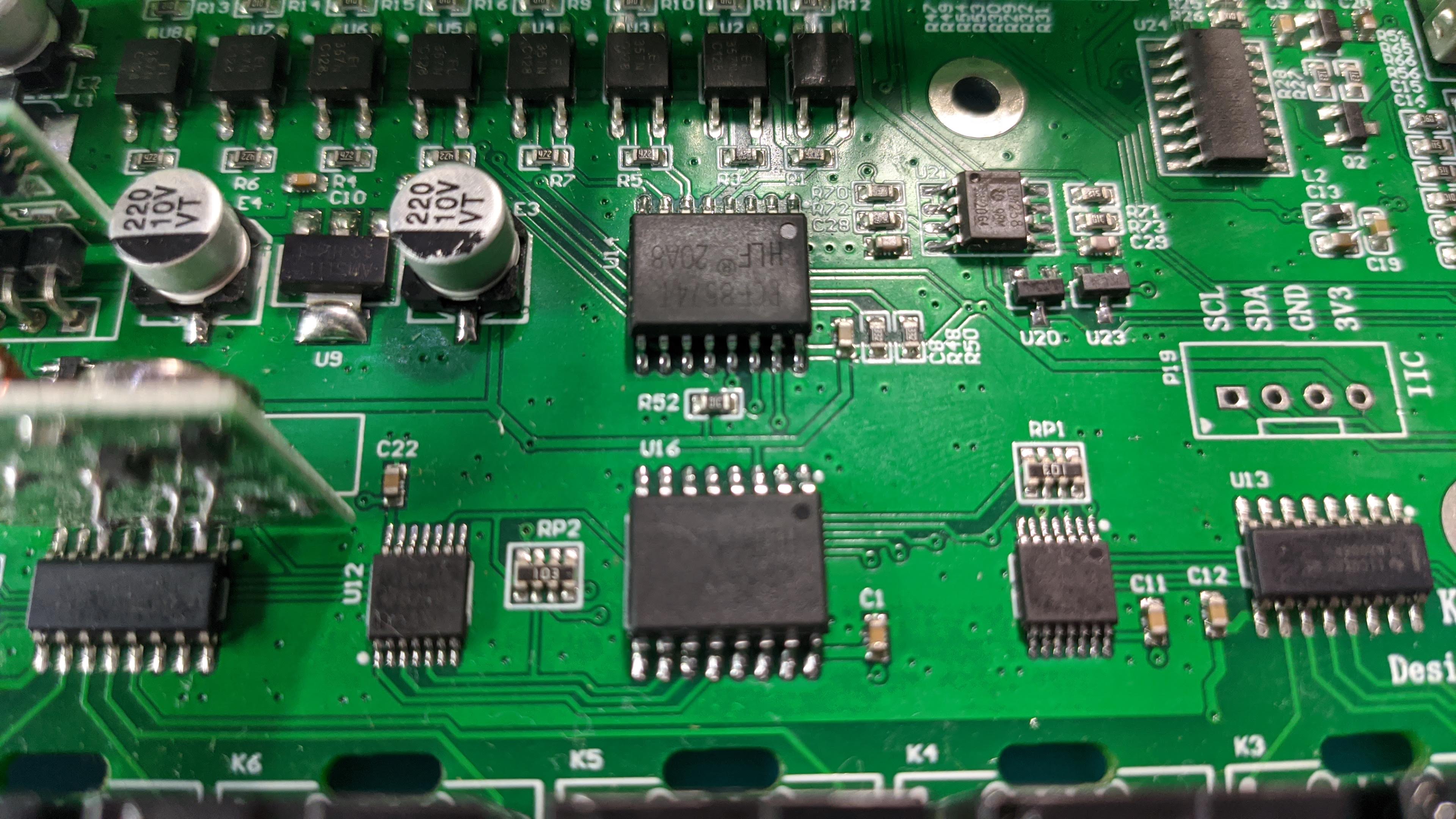
Further along, around the middle of the board are two PCF8574 I/O expanders. One is responsible for controlling the relays and the other one takes inputs from the 9 pin terminals marked as IN x in the features chart.
RF options is still available if you opt for the bundle with them. If not you can always use the headers for other purposes.
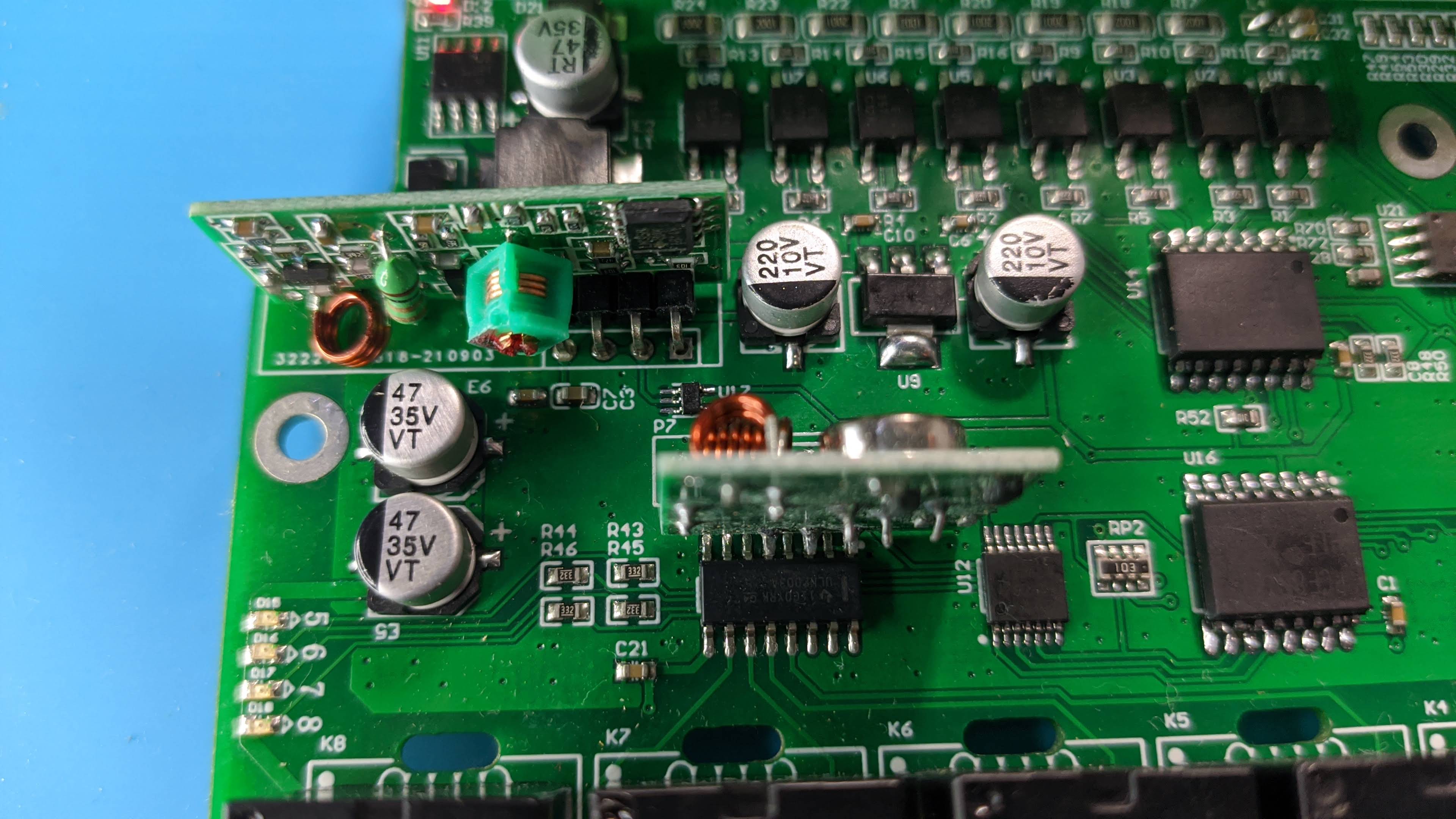
This time the digital inputs also have an additional 3.3v Vcc terminal to allow for easy adding of additional (non-I2C) sensors such as DS18b20 or DHT21.
Tasmota Configuration
Power the board using 12V terminals and use the mini USB to flash Tasmota via serial. Due to the choice of components you need to compile your own binary from the tasmota32 base and add the following to user_config_override.h:
#ifndef USE_I2C
#define USE_I2C                                  // I2C using library wire (+10k code, 0k2 mem, 124 iram)
#endif

  #define USE_PCF8574                            // [I2cDriver2] Enable PCF8574 I/O Expander (I2C addresses 0x20 - 0x26 and 0x39 - 0x3F) (+1k9 code)
    #define USE_PCF8574_SENSOR                   // enable PCF8574 inputs and outputs in SENSOR message
    #define USE_PCF8574_DISPLAYINPUT             // enable PCF8574 inputs display in Web page
    #define USE_PCF8574_MQTTINPUT                // enable MQTT message & rule process on input change detection : stat/%topic%/PCF8574_INP = {"Time":"2021-03-07T16:19:23+01:00","PCF8574-1_INP":{"D1":1}}

#define USE_ETHERNET                             // Add support for ethernet (Currently fixed for Olimex ESP32-PoE)
  #define ETH_TYPE          0                    // [EthType] 0 = ETH_PHY_LAN8720, 1 = ETH_PHY_TLK110, 2 = ETH_PHY_IP101
  #define ETH_ADDR          0                    // [EthAddress] 0 = PHY0 .. 31 = PHY31
  #define ETH_CLKMODE       3                    // [EthClockMode] 0 = ETH_CLOCK_GPIO0_IN, 1 = ETH_CLOCK_GPIO0_OUT, 2 = ETH_CLOCK_GPIO16_OUT, 3 = ETH_CLOCK_GPIO17_OUT

#define USE_RC_SWITCH                            // Add support for RF transceiver using library RcSwitch (+2k7 code, 460 iram)

#define USE_RF_SENSOR                            // Add support for RF sensor receiver (434MHz or 868MHz) (+0k8 code)
 #define USE_THEO_V2                            // Add support for decoding Theo V2 sensors as documented on https://sidweb.nl using 434MHz RF sensor receiver (+1k4 code)
 #define USE_ALECTO_V2                          // Add support for decoding Alecto V2 sensors like ACH2010, WS3000 and DKW2012 weather stations using 868MHz RF sensor receiver (+1k7 code)
After you get it running on your Wi-Fi network, set the template in Configuration - Other
{"NAME":"KC868-A8","GPIO":[32,0,1120,0,640,608,0,0,0,1,1,1152,0,0,5600,0,0,0,0,5568,0,0,0,0,0,0,0,0,1,1,0,0,1,0,0,1],"FLAG":0,"BASE":1,"CMND":"EthClockMode 3 | EthAddress 0 | EthType 0 | I2CDriver2 1"}
After applying the template you need one more configuration step. Navigate to Configuration - Configure PCF8574 and set the PCF8574 connected to relays to Output.
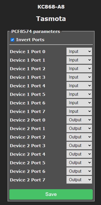
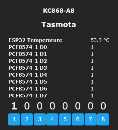
Relays will be mapped to POWERx outputs and behave like any other Tasmota relay. Input states will be displayed in the webUI and can be used as rule triggers.
To control relays with PCF8574 inputs you need to create rules for each input.
For example: Rule1 on PCF8574-1_INP#D0 do power1 %value% endon will mirror the value of the input with Relay1 aka PCF8574 output 0. Likewise you can use the same triggers to do other actions unrelated to relays.
Relays LEDs are tied to PCF8574 and cannot be controlled independently.
Both analog inputs and 4 digital inputs are left as user configurable in Configuration - Configure Module.
S2 button is mapped to Button1. If its not 100% reliable for you adjust the debounce setting with ButtonDebounce
Conclusion
This is a beast of a board and wired networking gives it an edge over any standard ESP board. It is an excellent choice for automating crucial parts of your setup where having Wi-Fi outages is unacceptable.
Visit Kincony AliExpress store to buy.

Explore more like this

Moes ES1 (ZSS-LP-HP02) Zigbee Human Presence Sensor Review
It was hard to resist the new Moes labelled sensor on AliExpress because it looked identical to the Linptech ES1 sensor which works with Xiaomi’s Mijia ecosystem but I avoided...


Comments