Kincony KC868-A4 ESP32 IR and RF 4 Channel Relay Board with Tasmota
One board to control it all!
Full disclosure: This is a sample sent to me free of charge by Kincony. Review is not influenced by that fact and is solely my opinion. Shopping links in this article can be affiliate links from which I earn a commission at no additional cost to you
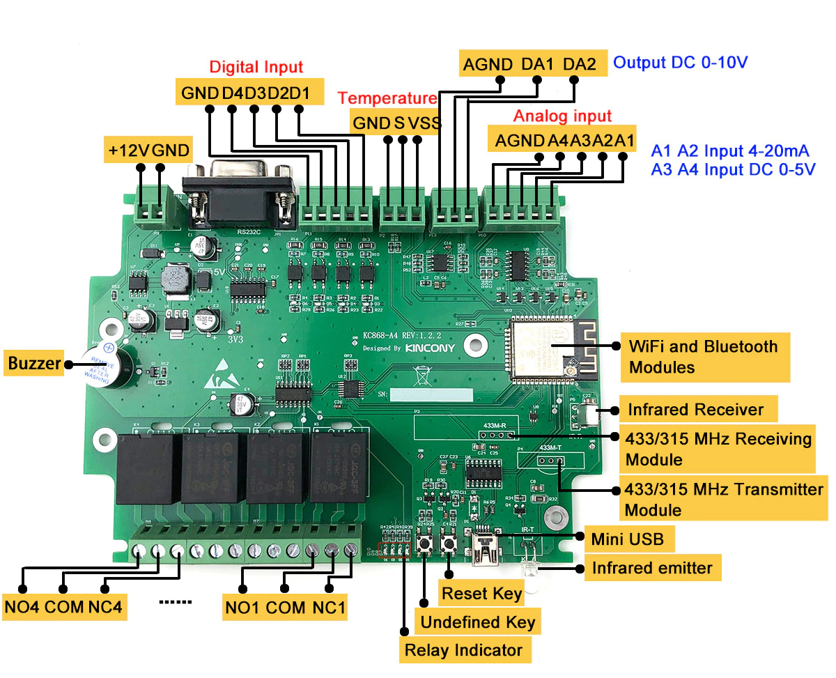
Kincony KC868-A4 is no ordinary 4 relay board, but instead comes jam packed with cool features. Alongside the already mentioned 4 NO/NC 10A relays there’s IR send and receive, RF send and receive, 4 optocoupler isolated digital inputs, 4 analog inputs, one wire temperature sensor terminal, 2 DAC 1-10v outputs, RS232 port and a buzzer. All that controlled by ESP32 so you get Bluetooth on top of all that. Board is powered only by 12V DC.
It is available from Kincony AliExpress store in a couple bundle options including an optional DIN enclosure.
Features
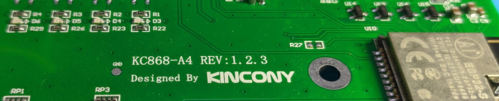
I received the basic board version which comes without the RF components. Two things immediately jumped out at me. The RS232 port and the mini USB plug. Yes, those old things!
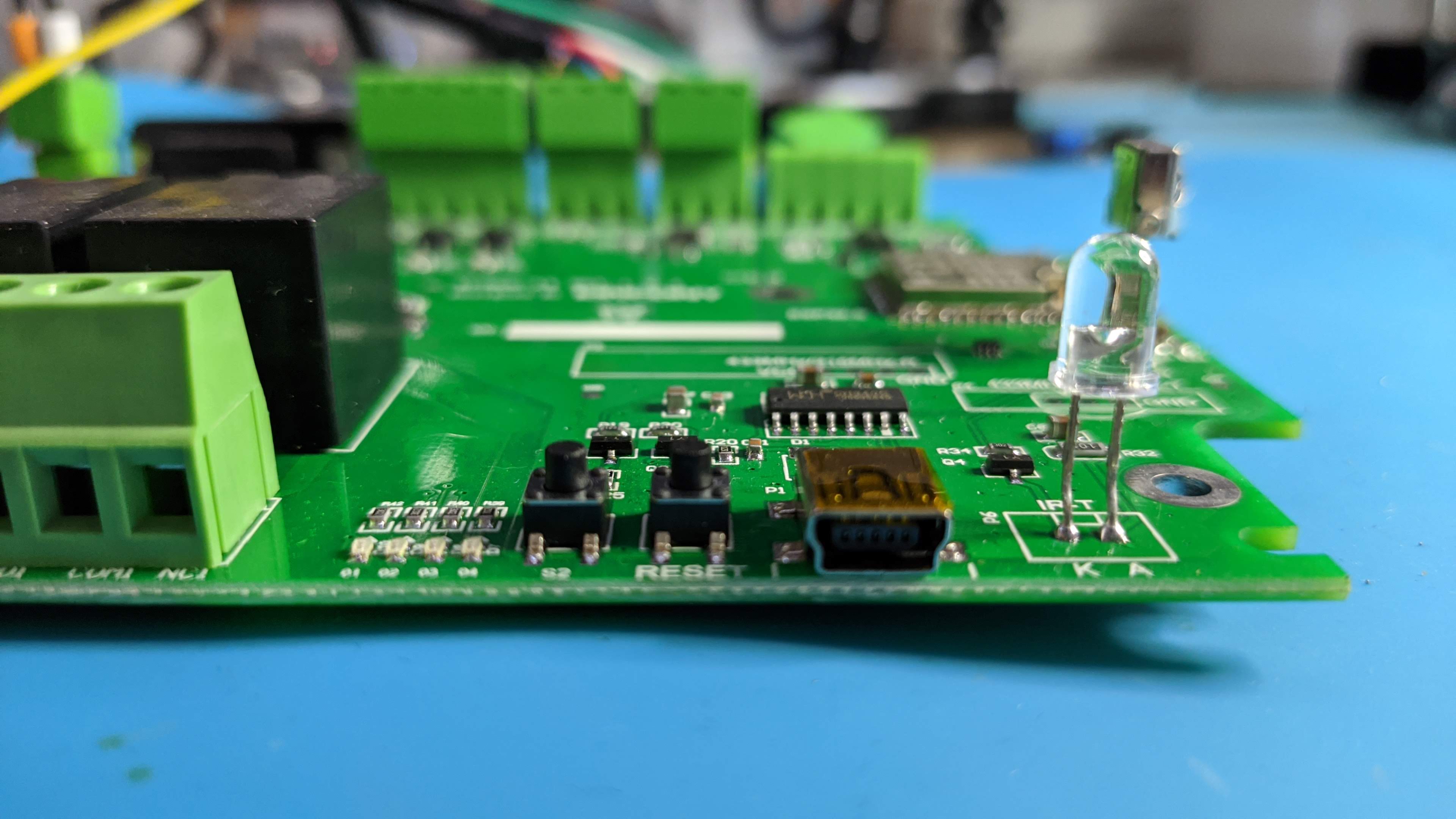
I don’t know what’s the justification for having a mini USB port but its the only option given. I didn’t even know if I had a mini USB cable so I had to rummage through some dusty “computer stuff” boxes. Luckily my “never throw computer stuff away” rule is beneficial in this situation and I found a couple of them
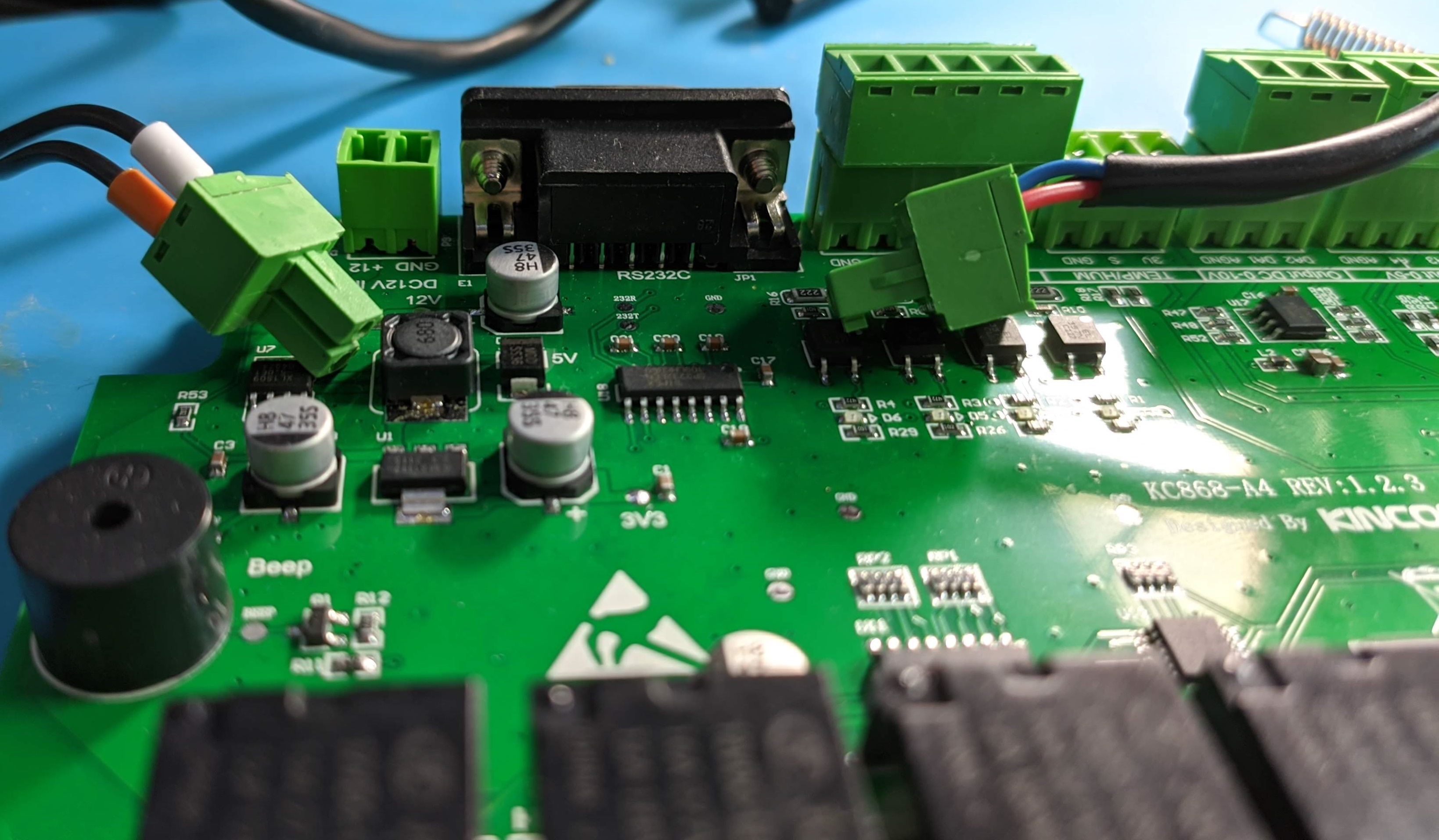
To power the board use the top left terminals labelled +12. These pluggable terminals are by far my favourite feature on this board. They make working with it very enjoyable and there’s no need to fiddle with the screwdriver at weird angles when connecting the wires.
The 4 relays have terminals for normally open and normally closed configuration. They’re rated up to 10A/277VAC or 12A/125VAC.
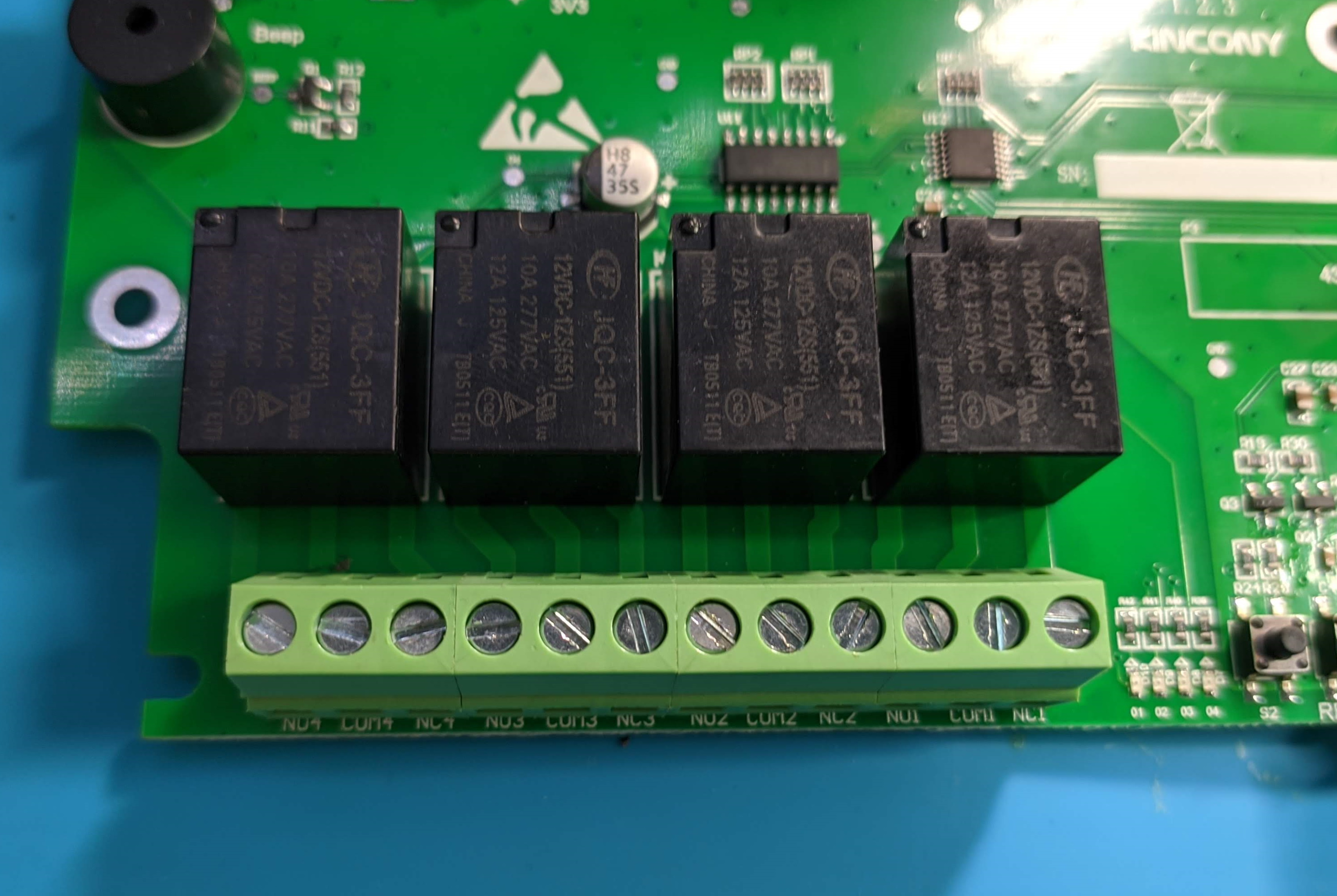
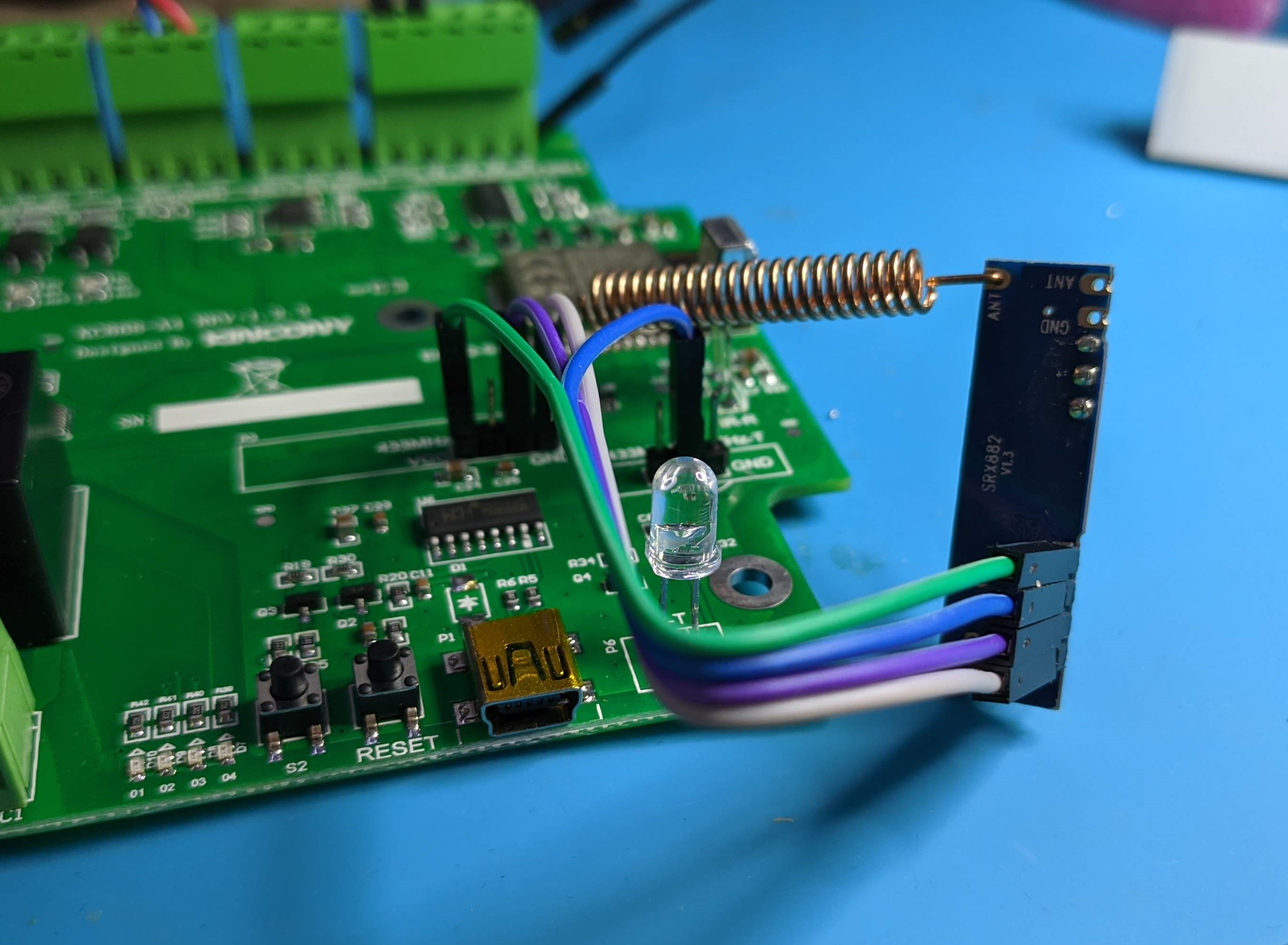
At the bottom right, next to the mini USB port is the IR receiver (IR-R) and the IR LED (IR). The unpopulated pin holes are for the RF transmitter and RF receiver. You can choose between 433Mhz and 315Mhz boards but Tasmota will support only 433Mhz. I’ve used the standard SRX882 and STX882 but ran into an issue with the RF receiver. On the board the CS and DATA pins are connected together but that does not work well with Tasmota. You have to pull the SRX882 CS pin high to enable it. For that I used the RF transmitter’s middle 3.3v pin as a quick problem solution.
Kincony says that the RF Receiver that comes in the bundle should work with default headers
It’s 2021 and I don’t really see use for the RS232. In my mind it’s a big waste of space. I would’ve loved to see an I2C header instead, maybe with a Grove connector or a 2.54 JST one. Would’ve greatly increased the options for the board.
A big thorn in the eye is a lack of VCC terminals. Currently there’s no dedicated or practical way to get 5V power unless you count the tiny debug pad above the buzzer. 3.3V is kind of available on the TEMP/HUM terminal. There’s enough room on the board, especially next to the power cluster for a couple of headers to offer 5V and 3.3V power would’ve been more than welcome instead of leeching from random solder points.
Tasmota Configuration
Power the board using 12V terminals and use the mini USB to flash Tasmota via serial. To do it the simplest way possible, visit Tasmota Web Installer, select Tasmota from the dropdown and click install. Yes, it is that easy!
After you get it running on your Wi-Fi network, set the template in Config - Other
{"NAME":"KC868-A4","GPIO":[32,0,227,0,224,225,0,0,0,1312,1,226,0,0,480,1152,0,1120,1056,1088,0,1,1,1,0,0,0,0,4706,4707,4704,4705,1,0,0,1],"FLAG":0,"BASE":1}
The TEMP-HUM terminal is set to DS18B20 temperature sensor, if you’re using a different sensor, change the Template.
Analog and digital inputs and DAC output (GPIO25 and GPIO26) are configurable in Configure Module.
S2 button is mapped to Button1 and you can use it to control all 4 relays using the multi press. It was not 100% reliable in my case so it might need some adjustment using ButtonDebounce
To use the DAC output to output constant voltage you need to use Berry scripting.
What can it do?
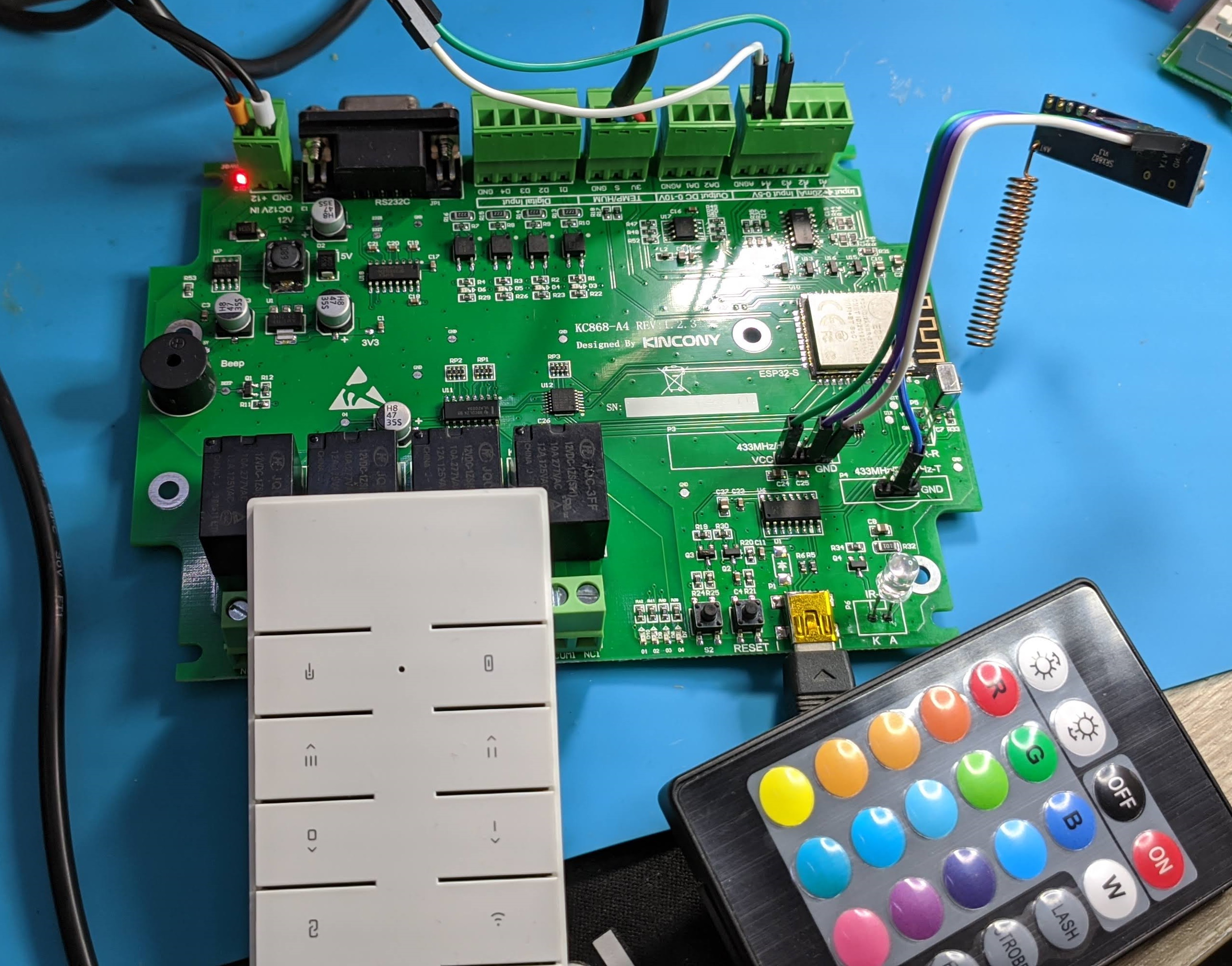
I’ve repurposed an IR remote from the Sonoff L1 Lite review and a Sonoff RM433 RF remote for playing with the Kincony board.
A DS18B20 temperature sensor is connected to TEMP/HUM terminals and an analog moisture sensor to A4 terminal powered with 5V from the 5V debug pad.
With this board you can translate IR codes to RF codes and vice versa. The control combinations are vast.
Conclusion
I really like this board despite a lack of 3.3v and 5v headers. The multitude of control combinations possible with this board is its biggest strength.
Visit Kincony AliExpress store to buy.

Explore more like this
Moes ES1 (ZSS-LP-HP02) Zigbee Human Presence Sensor Review
It was hard to resist the new Moes labelled sensor on AliExpress because it looked identical to the Linptech ES1 sensor which works with Xiaomi’s Mijia ecosystem but I avoided...


Comments