Frankenstein Saturday 3: ESP-12 Drop-in Replacement
How to flash an ESP-12 module and make a drop-in replacement of a nonESP82xx Wi-Fi module for which you don’t have any datasheet or pinout.
Why even do this?
I found some dirt cheap Wi-Fi CCT bulbs that claims 15W 1500lm and an above average color range of 2000K to 7000K. All that for around 5$ per bulb. There must be a catch…
First sign there is, is that it uses the “Cloud Intelligence” app which could mean no Tuya-Convert.
Taught by my previous experience with a Techlife bulb I also expected it wouldn’t be using an ESP module.
Whatever, it’s five bucks, so no big loss for trying. I ordered two!
Teardown
They arrived in a generic bulb box without any model numbers and there is nothing printed on the bulb either. I did manage to find “Fcmila” mentioned on the tiny sticker on the box which is a name I recognise. From now on it shall be known as Fcmila 15W CCT bulb. The bulb itself is quite light. All in all, not a great first impression but not terrible!
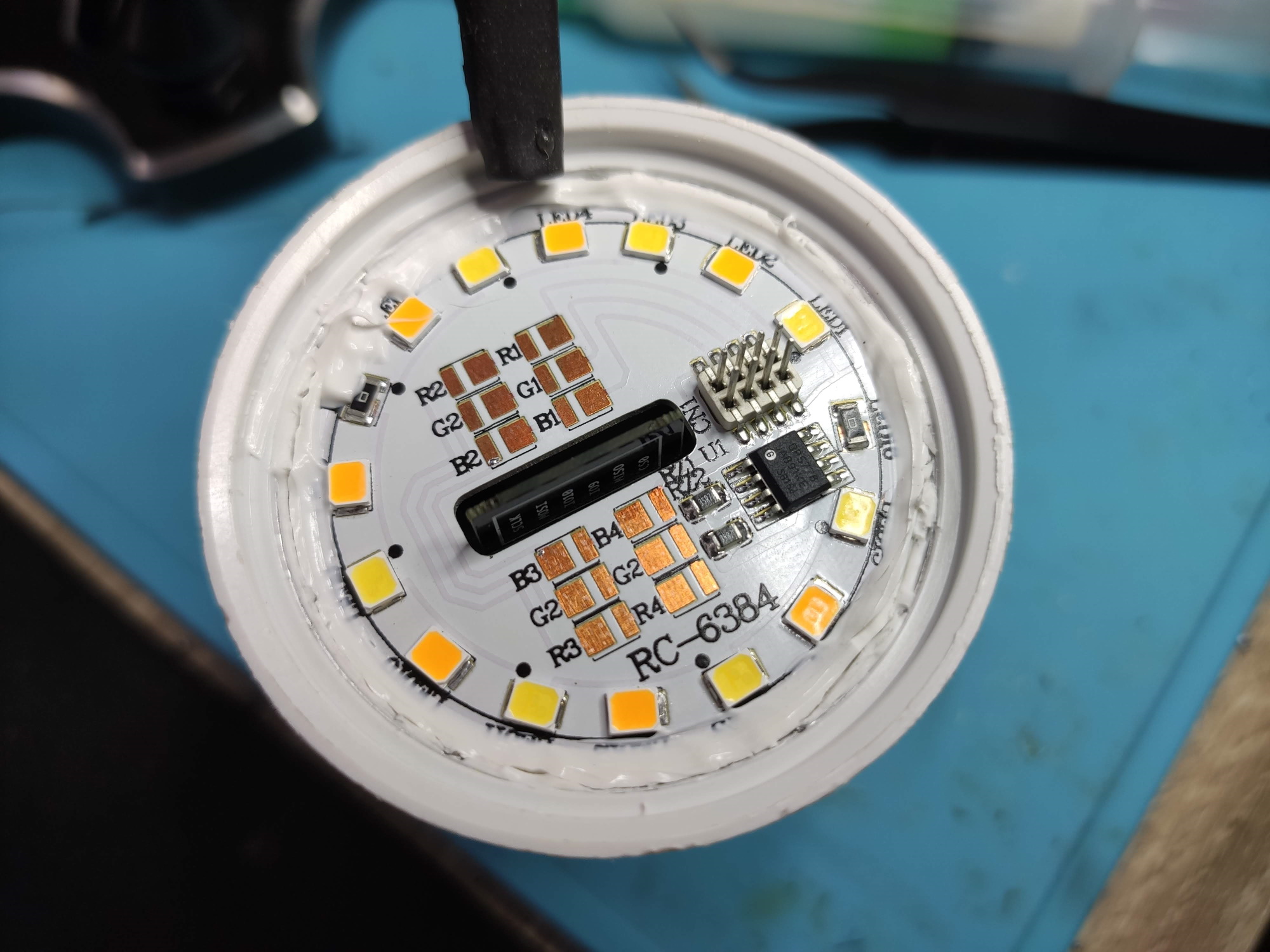
I immediately tried to disassemble it and the diffuser dome popped off with ease. The LED PCB is glued to the bulb base so I went around the entire base with a knife to cut it. The top can be easily pried up, it is connected to the main PCB with the visible headers.
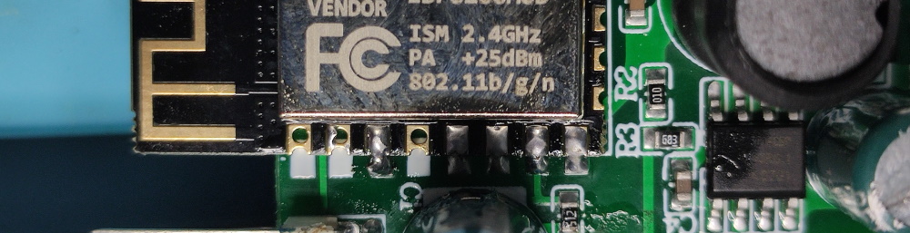
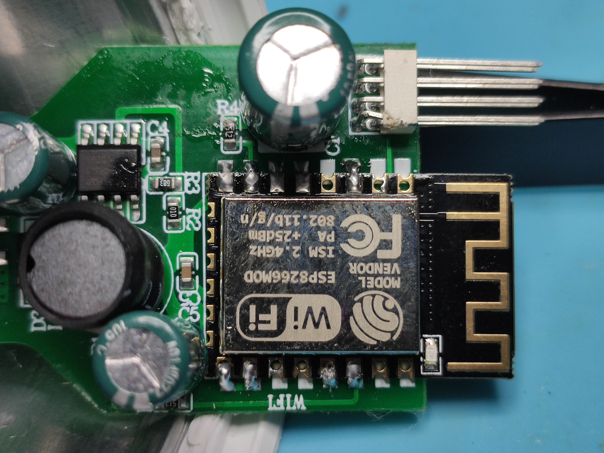
The main PCB holds the power supply and the unknown Wi-Fi module. The nice thing is that its connected to the E27 screw base with wires and it can be slightly pulled out of the plastic enclosure to make it easier to work with.
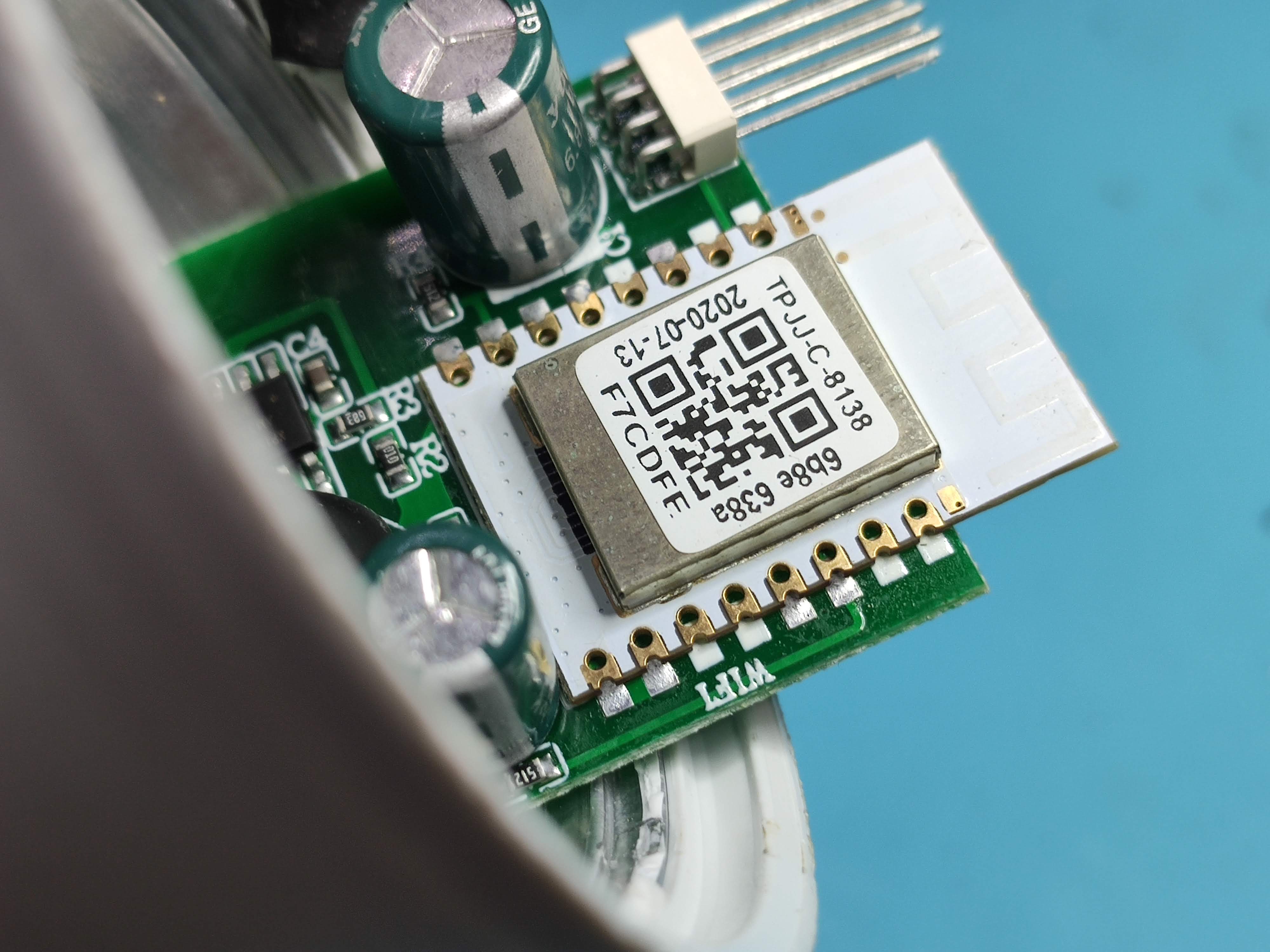
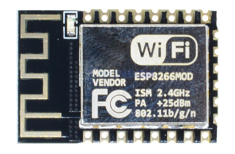
The module has a lot of markings but googling any of those didn’t reveal anything. Notice the date: 2020-07-13. Freshly made Wi-Fi modules are the best! Time to find out the manufacturer using the MAC address. For that it needed to connect to my Wi-Fi which means I have to use the bulb it how it was intended, with the Cloud Intelligence app. Ew!
Connecting to the terrible Cloud Intelligence app was painful. Registration took forever, paring process took forever and I had to resort to using the alternative pairing mode in the end. The app is laggy and commands take a few seconds to come through. The app itself looks like a ripoff of Tuya Smartlife app, not sure if its a good thing or a bad thing.
On a positive note the bulb is nice and bright and the color temperatures look good so it should be worth replacing the Wi-Fi module. Anyway, back to the topic…
After connecting to the separate Wi-Fi network I took the MAC address and ran it through MAC vendor lookup which revealed the module belongs to Shenzhenshi Xinzhongxin Technology Co.. Finding a datasheet was impossible.
Time to go deeper by removing the metal shield on the module. That gave another clue by revealing its using a C-Chip CC8000 Wi-Fi chip. Never heard of it? Me neither and apparently neither did Google.
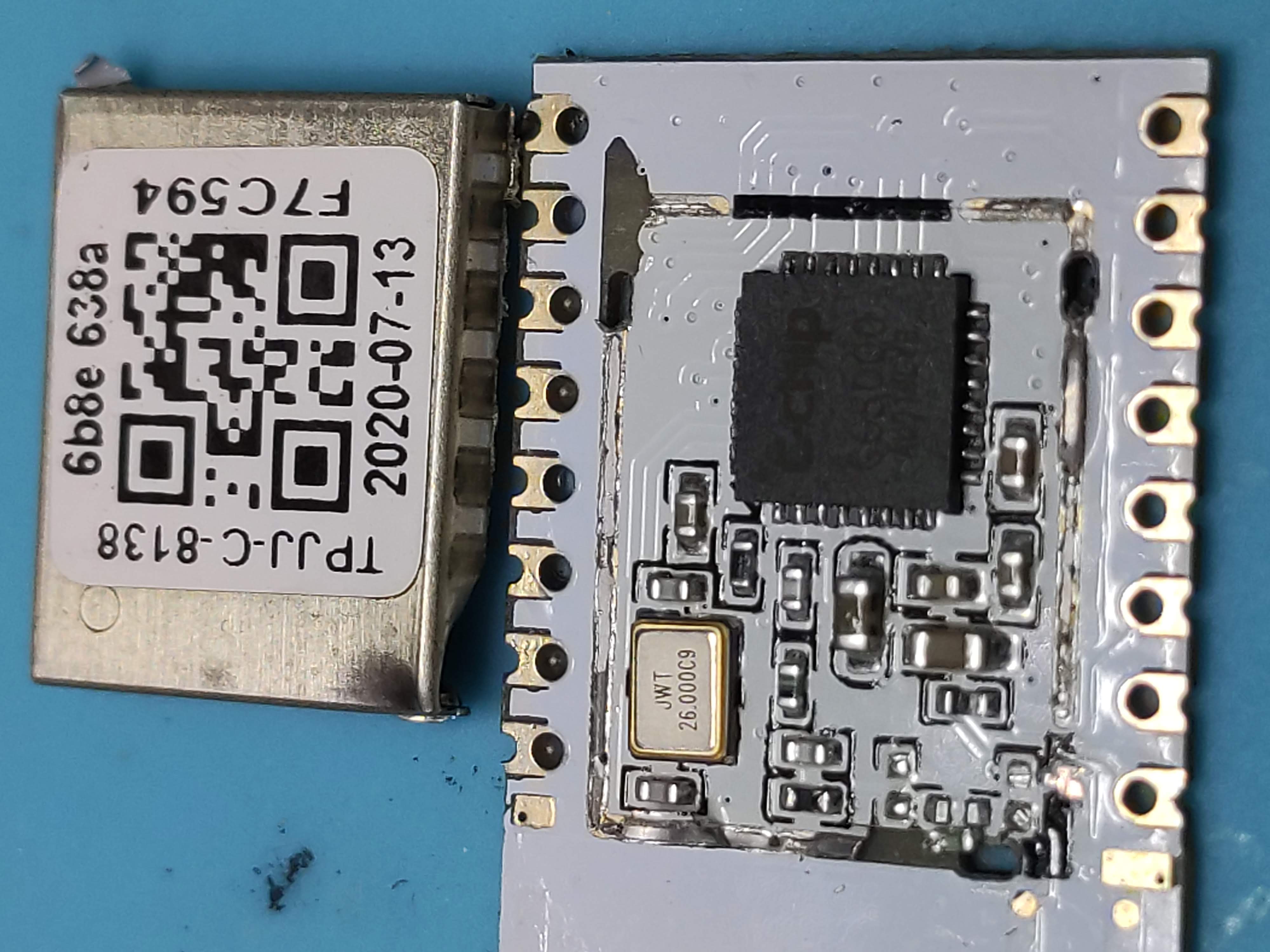
Next step, remove the module from the board. Maybe its has marked pins on the back like many ESP82xx modules do. That is doable even with a simple soldering iron thanks to this video but I got a simple soldering heat gun instead. I sense this procedure might happen a lot more with the glut of new Wi-Fi modules.
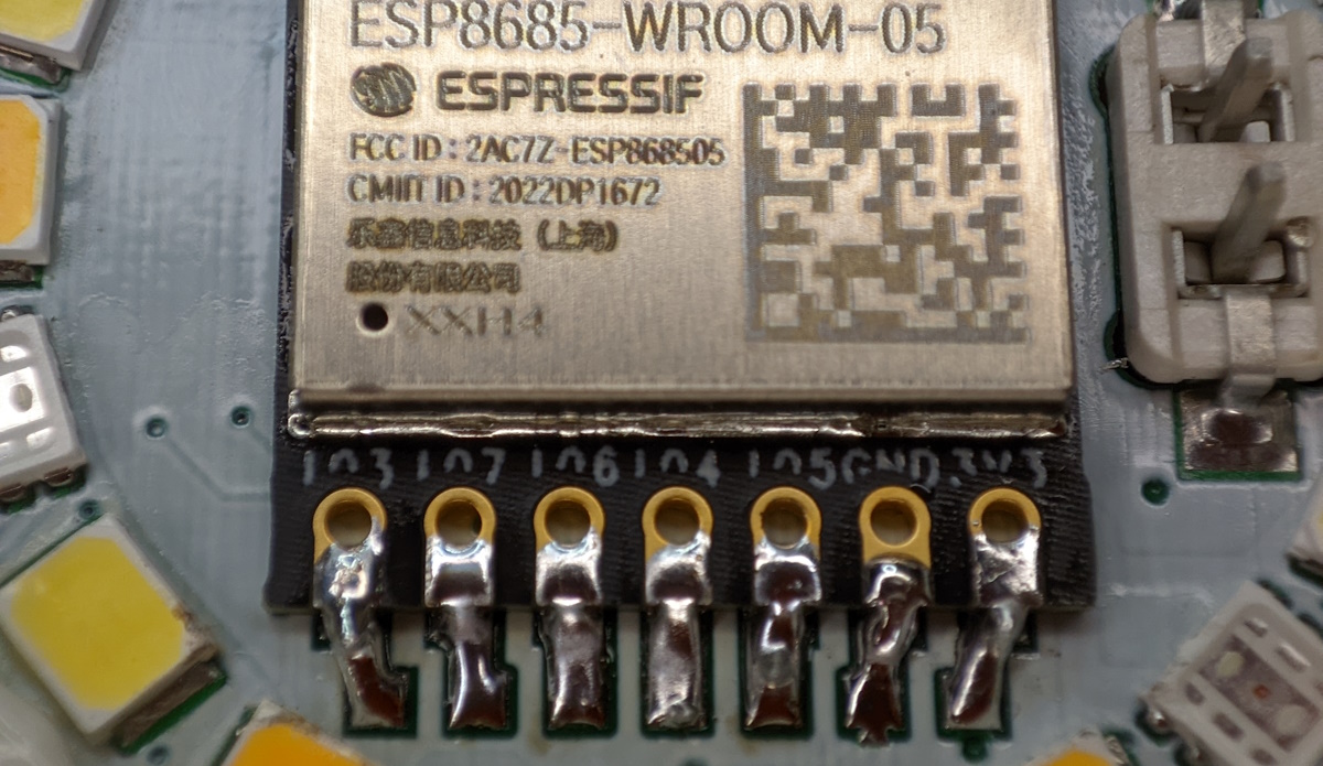
Removing the module was a good move, it revealed which pins are connected to the bulb and also that the layout looks very similar to an ESP-12 module. All signs point to: “This should work”.
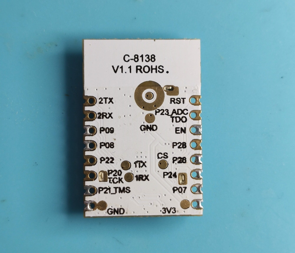
First to test the theory. Soldered some wires to the PCB pads that were connecting to CC8000 3V3, GND, P07 and P09 marked pins. Then I connected the wires to a NodeMCU with Tasmota flashed on it. Reconnected back the LED PCB and screwed the bulb into a bulb receptacle. Put it as far away as possible and powered it on. Yes, that’s being mains powered and that’s why its far away.
NodeMCU powered up which is good. After configuring the pins to PWM1 and PWM2 (which is a CCT light) the lights turned on. Pins are correct and it’s time to make a permanent change.
Flashing ESP-12
I had a bunch of ESP-12F modules but any ESP-12x will work. Flash the module with Tasmota before soldering it to the bulb.
Flashing a bare ESP-12x is a bit more involved than your typical ESP board. Many tutorials make it look very complicated with buttons, resistors, breadboards but it can be a lot simpler than that. If you have an ESP-12 module type with the holes like ESP-12F you can just use regular dupont cables and push them in with a bit of force then wire them up using a small breadboard using this wiring schematic.

Once you got it flashed and configured Wi-Fi, it is ready to go to its new home.
Replacing the old module
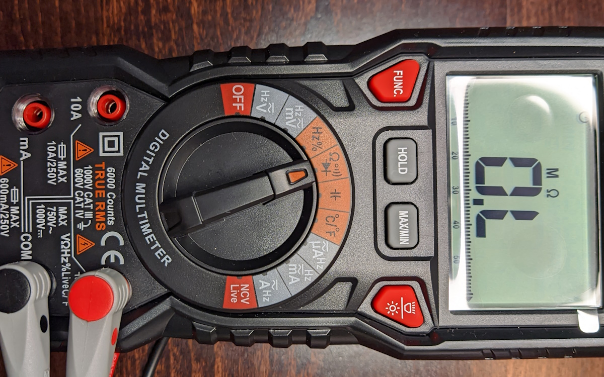
All ESP-12x modules need the GPIO15 pulled low and CH_PD or EN pin pulled high to boot normally. It is best to check with a multimeter whether the previous module had similar requirements and that those pins have continuity with GND for low and VCC for high. If not you will have to connect them with some wire or whatnot.
With this module the requirements were the same and it was just a simple matter of soldering in the ESP-12F to all the tinned pins.
Remove the LED from the ESP-12F if you don’t want your bulb to have a blueish flash when powered on.
Everything is set. All that remains is to reassemble the bulb, power it on and find out the right PWM pin assignment. Here’s the modified bulb’s Tasmota template:
{"NAME":"Fcmila CCT","GPIO":[0,0,0,0,0,37,0,0,0,38,0,0,0],"FLAG":0,"BASE":18}
Cheapest ever CCT bulb, now Tasmota compatible.

Explore more like this
Convert Xiaomi MMC MHO-C401 E-Ink Bluetooth Sensor to Zigbee
Guide on installing Zigbee firmware on the Bluetooth temperature and humidity sensor with e-ink display. The best Zigbee temperature and humidity sensor with an e-ink display is a Bluetooth one....
Kaiweets HT118A Digital Multimeter Review
If you’re into tinkering with electronics one of the tools you can’t go without is a multimeter.
Comments