Replace Tuya CB2L, WB2L, BW2L Modules with ESP
Summary
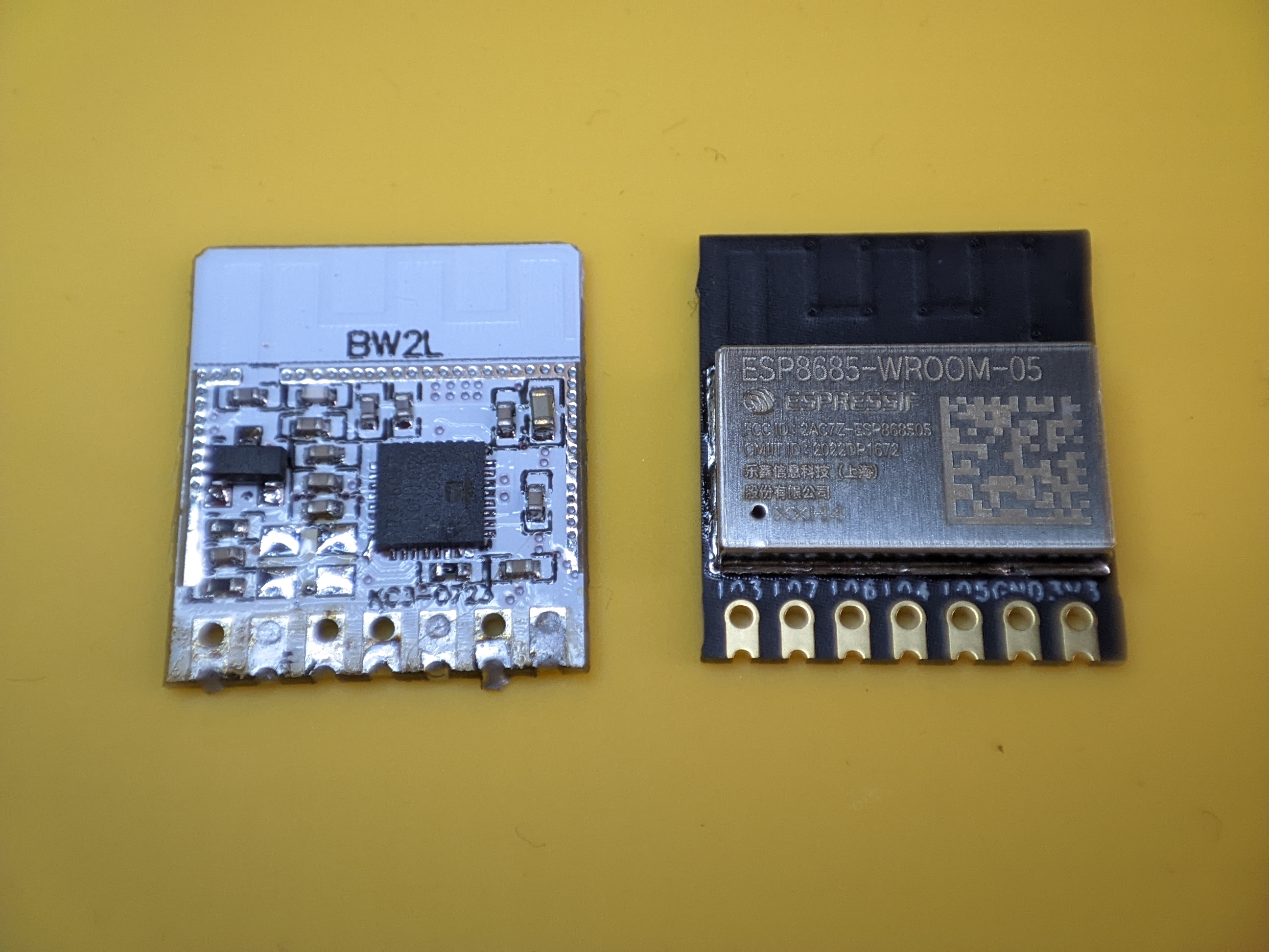
Replace Tuya TYWE2L, CB2L, WB2L, WR2L, WBR2L, BW2L and similar Wi-Fi modules with an Espressif ESP32 or ESP8266 light module.
Full disclosure: Links to Amazon, AliExpress and Banggood are affiliate links and I earn a small commission when you buy through them which helps fund future projects and reviews
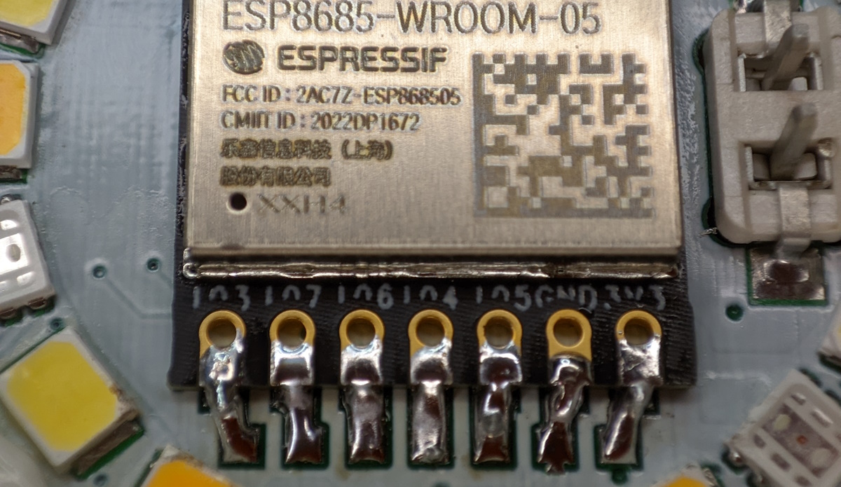
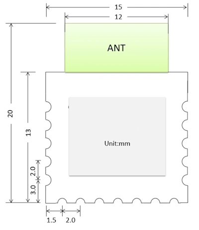
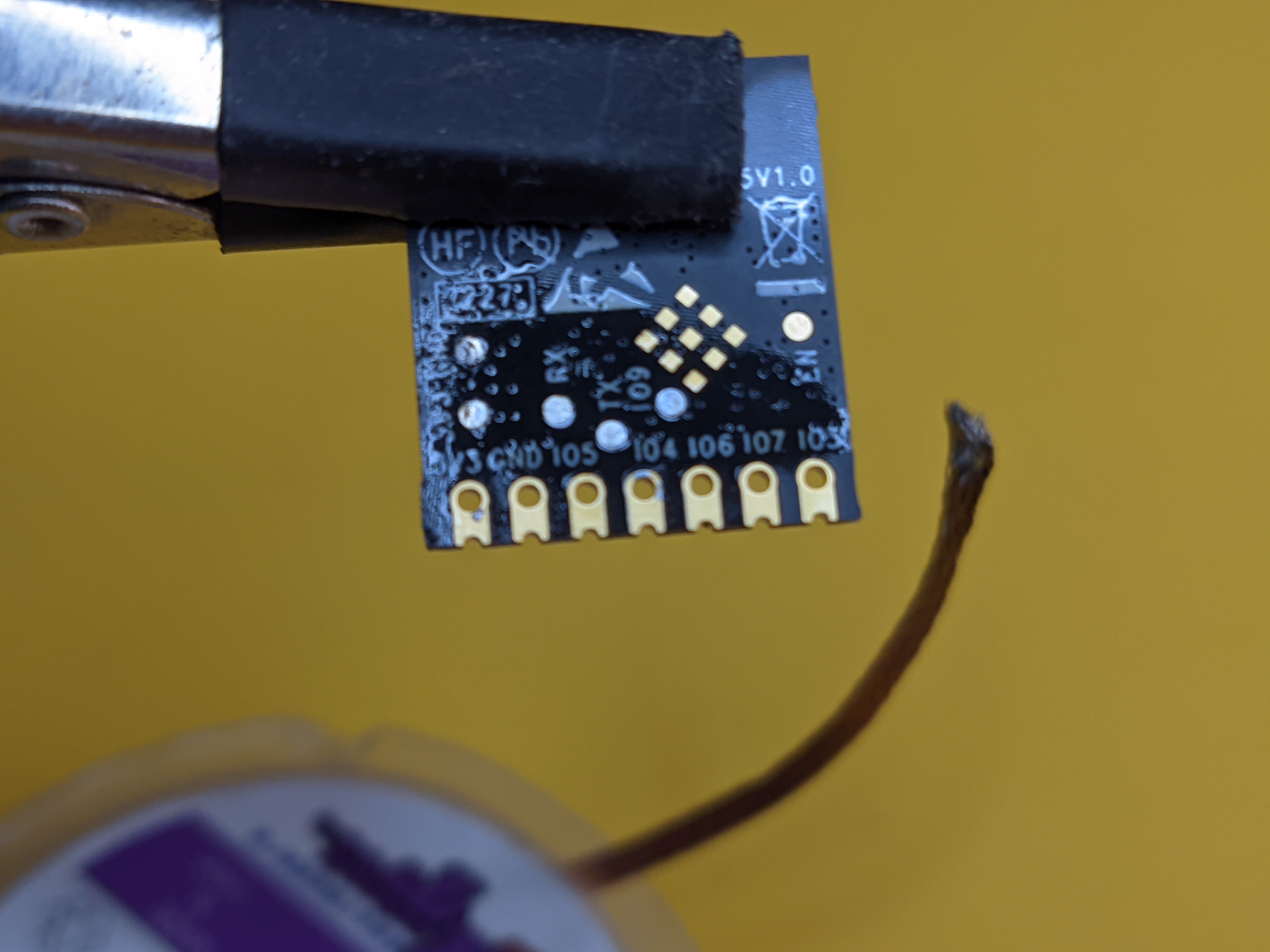
All the listed modules have a similar footprint and same pinout for pins labelled in the image.
For this you will need the following:
- soldering heat gun aka rework station - I use the JCD from AliExpress. You can try without one but it’s harder than it looks in the video.
- a soldering iron - I recommend a modern pen style iron with TS or T12 tips such as Sequre Si012 (AliExpress, Amazon*, Sequre, Banggood, ), PTS100 (AliExpress, Banggood) or Pinecil (Amazon)
- good solder and flux - don’t get the super cheap stuff and definitely don’t use unleaded solder. I typically get Mechanic brand from AliExpress and also their RMA223 flux.
- desoldering braid - not a must have but helps in cleaning up old solder. Mechanic brand from AliExpress of course.
- IPA for cleaning
- serial to USB flasher to flash the new module. I use Soldered Connect Programmer with a good voltage regulator but a cheap CH340G one from AliExpress or Amazon or any other flasher board will be enough.
- ESP module:
- ESP8685-WROOM-05 - ESP32-C3
- DT-ESP-C05 - ESP32-C3
- DMP-L1 - ESP8266
- ESP8684-WROOM-05 - ESP32-C2
Work on a heat resistant surface. I use a cheap cooking silicone mat (AliExpress).
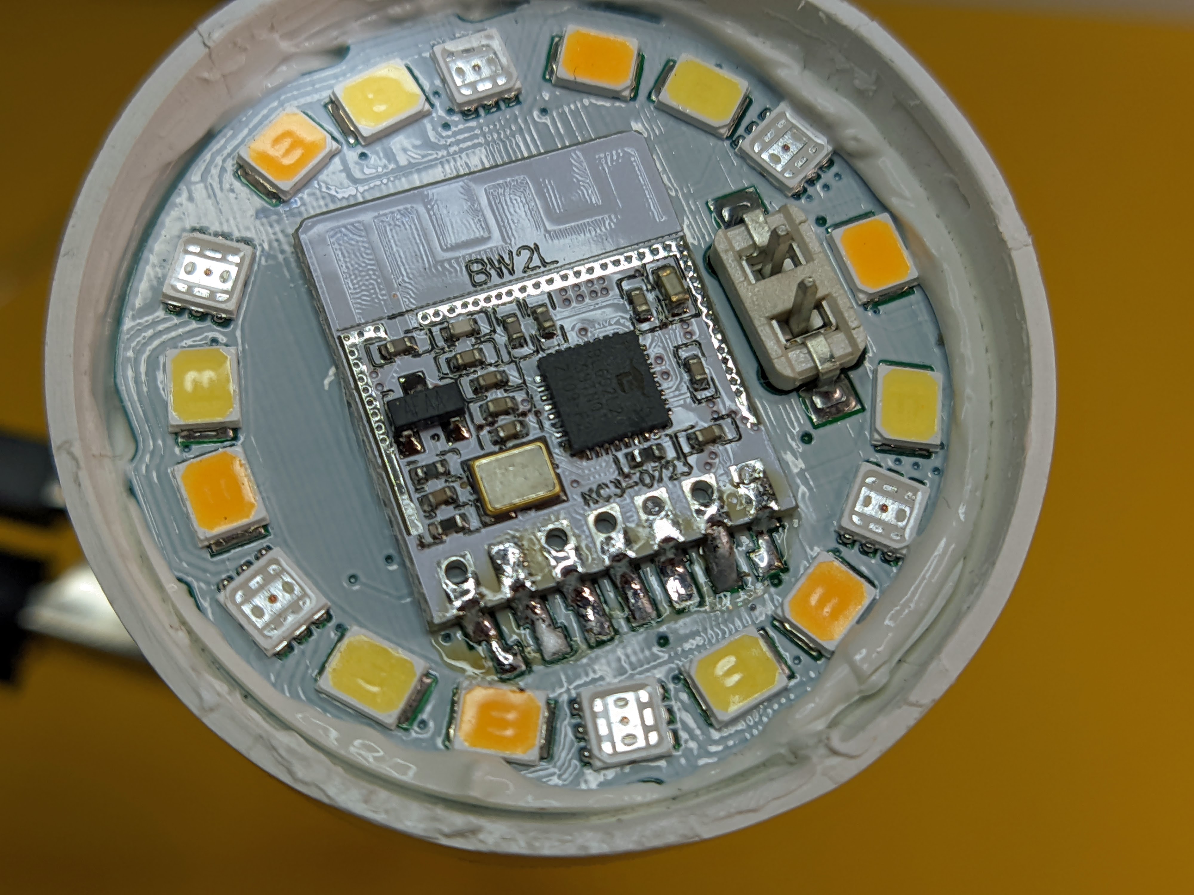
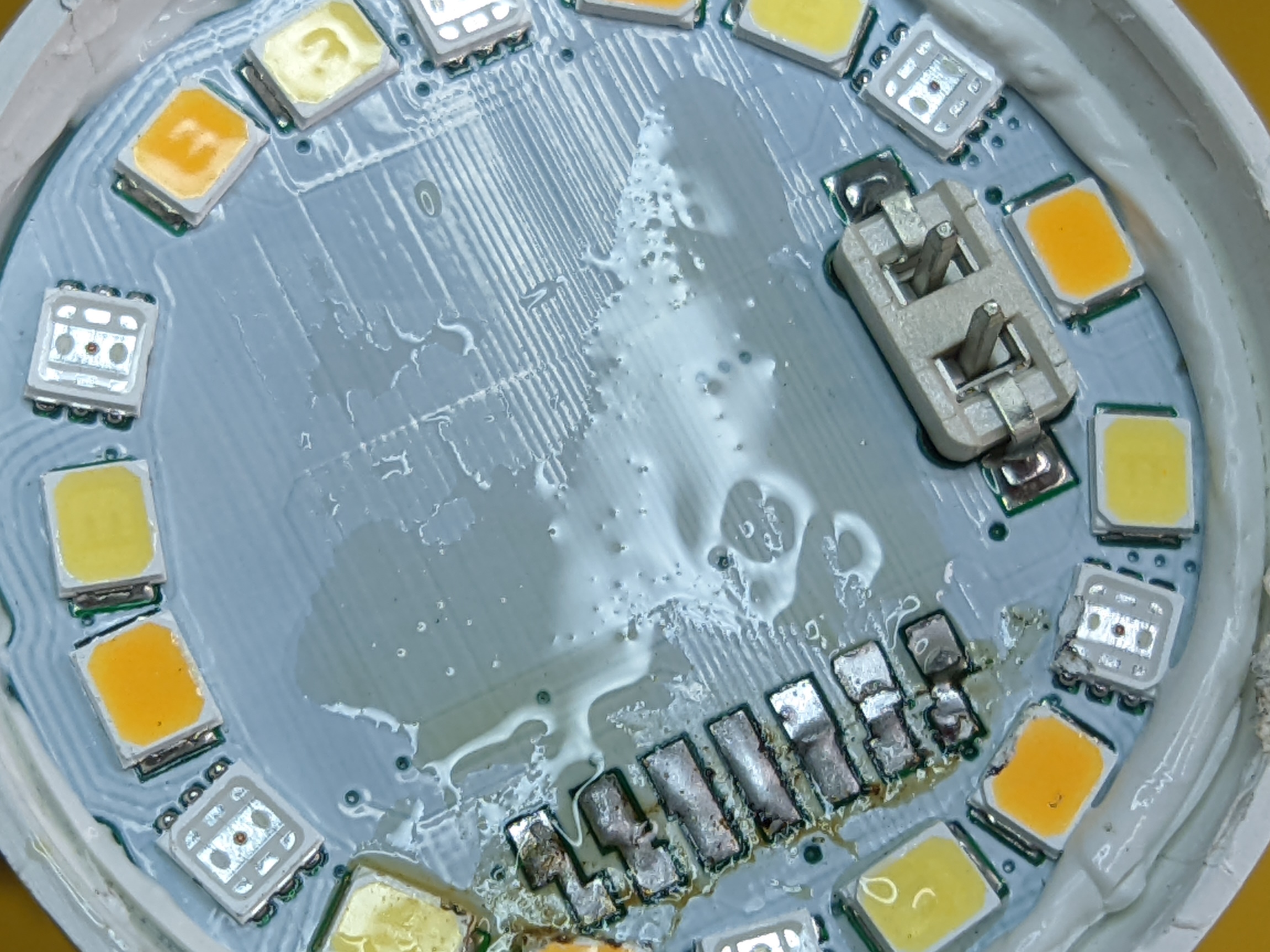
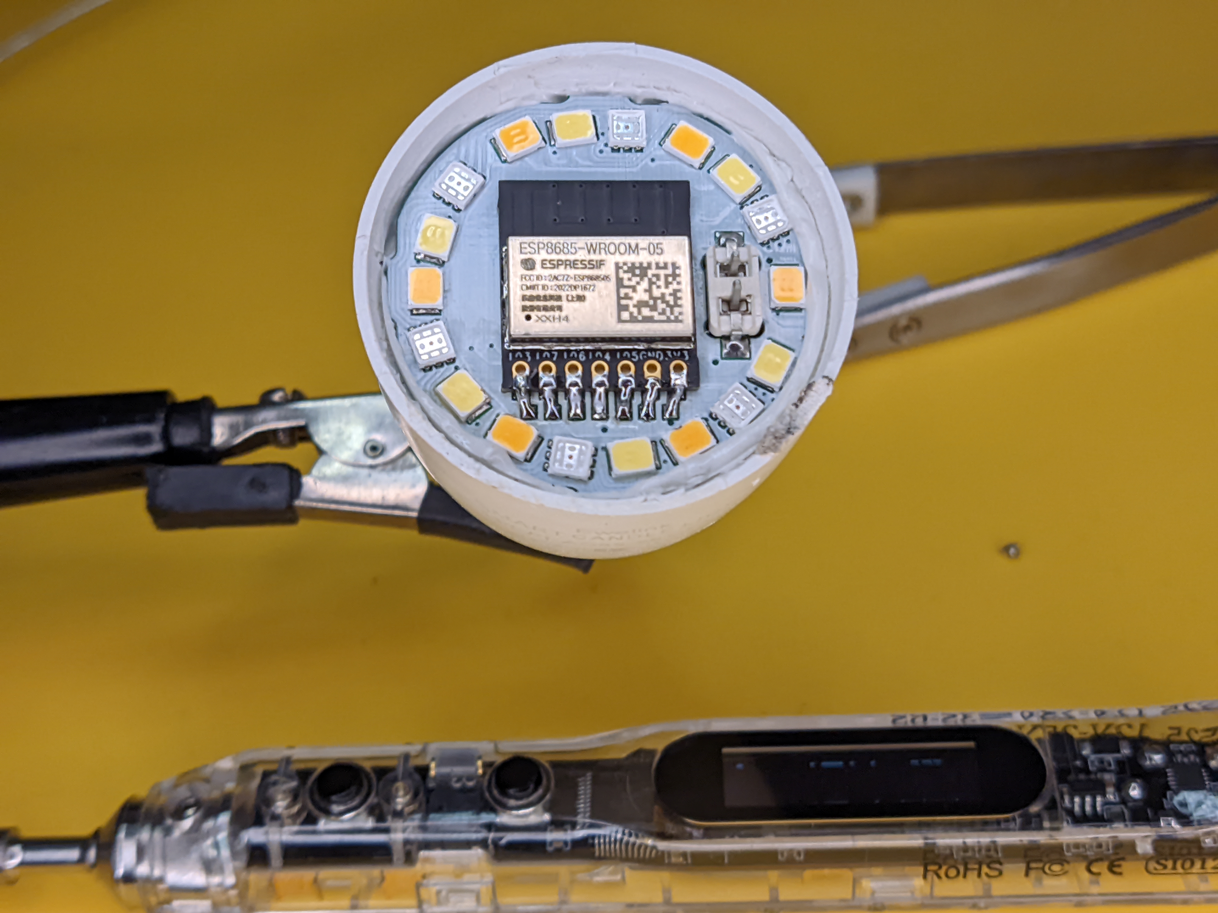
Disassemble the device and take the PCB out if it makes it easier to work with. This example features the eWeLink E14 Candle bulb.
Put flux on the bottom row of pads and solder them liberally. The leaded solder you use will mix with the factory non-leaded solder and that will bring down the melting point and make the process faster and smoother.
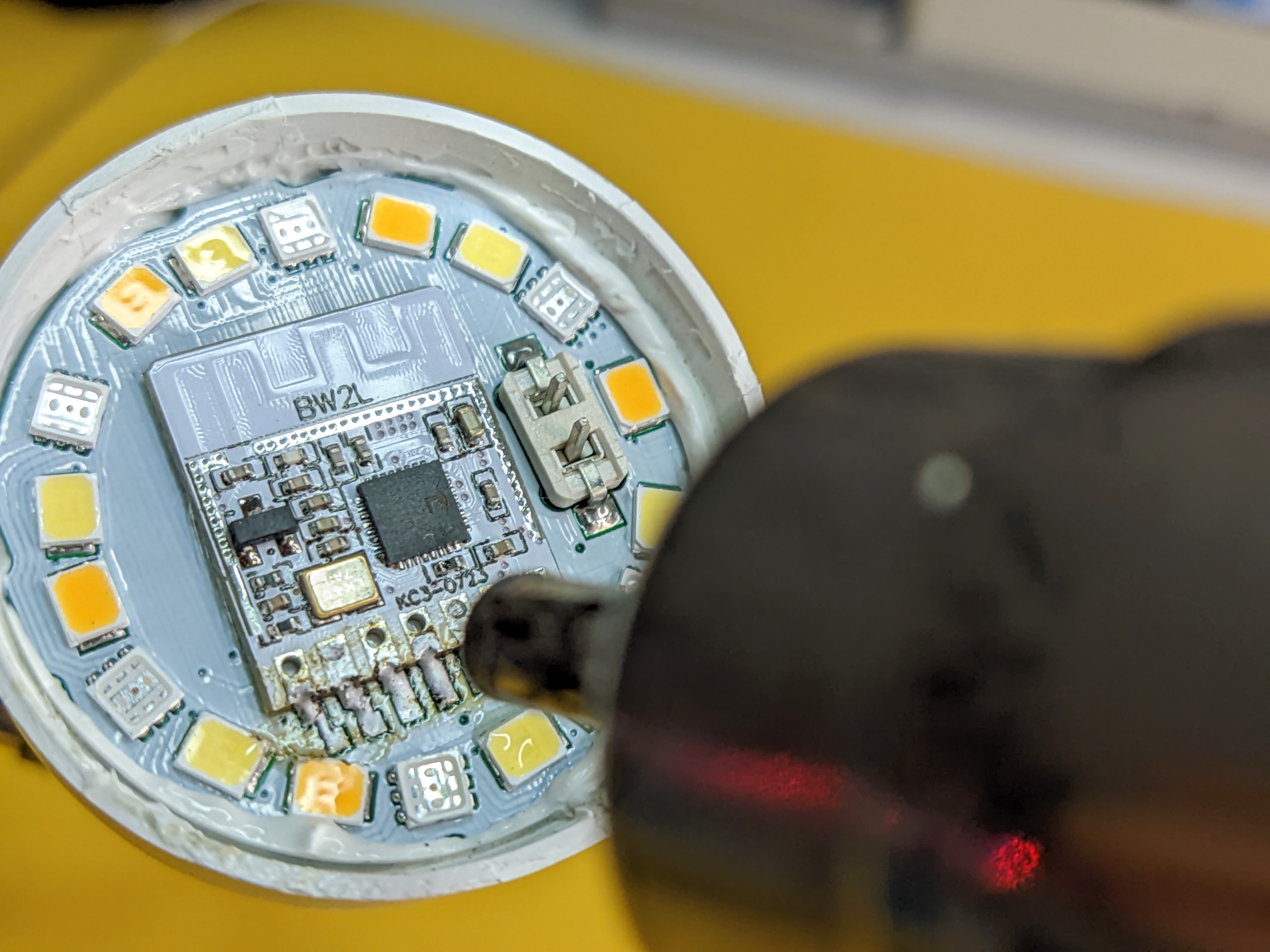
Set the heat gun to 350-400°C and start moving it left to right on the bottom of the module. Once you see the solder liquifying, nudge the module up with tweezers or whatever you have handy.
DO NOT apply a lot of pressure and force it, that will only result in torn pads. If everything has heated up to the right temperature the module will slide off.
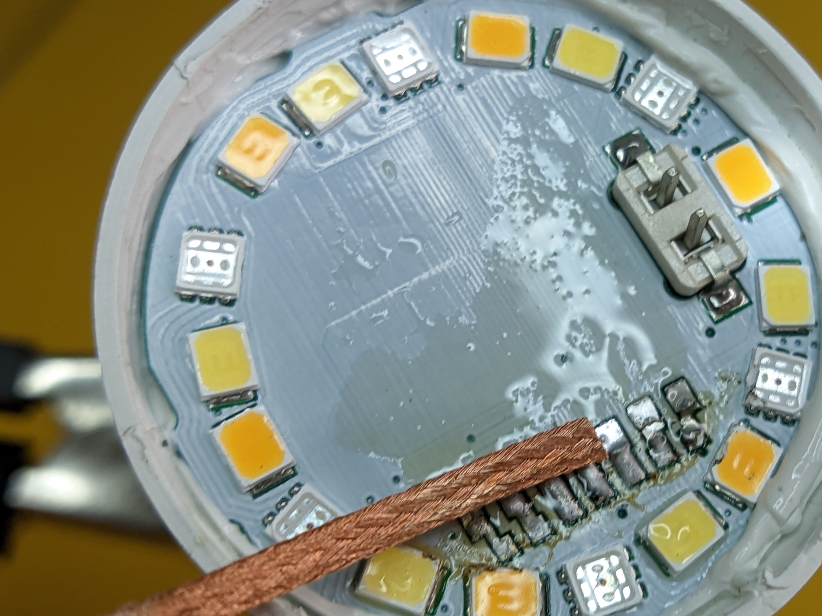
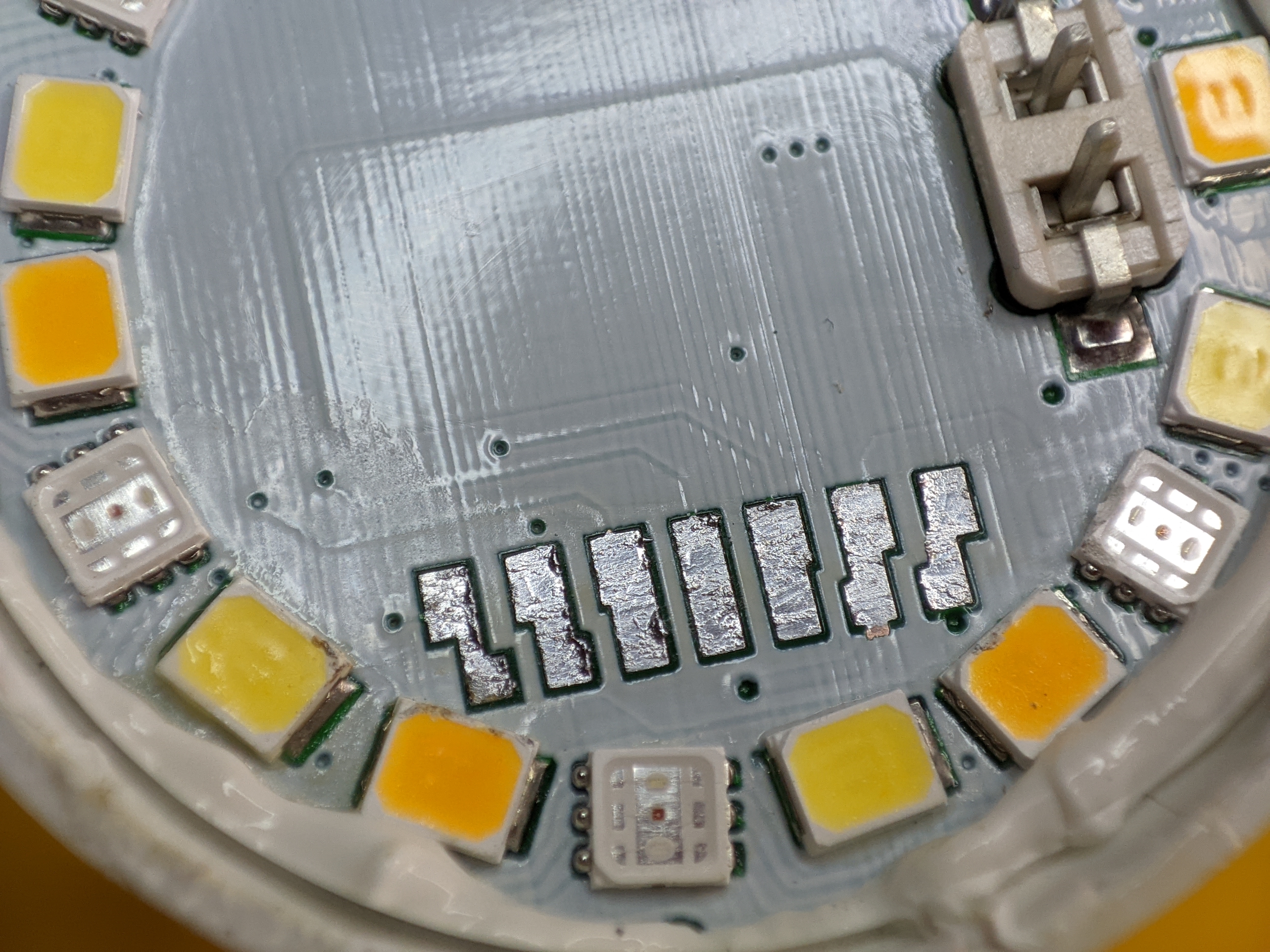
Clean up left over solder with the desoldering braid.
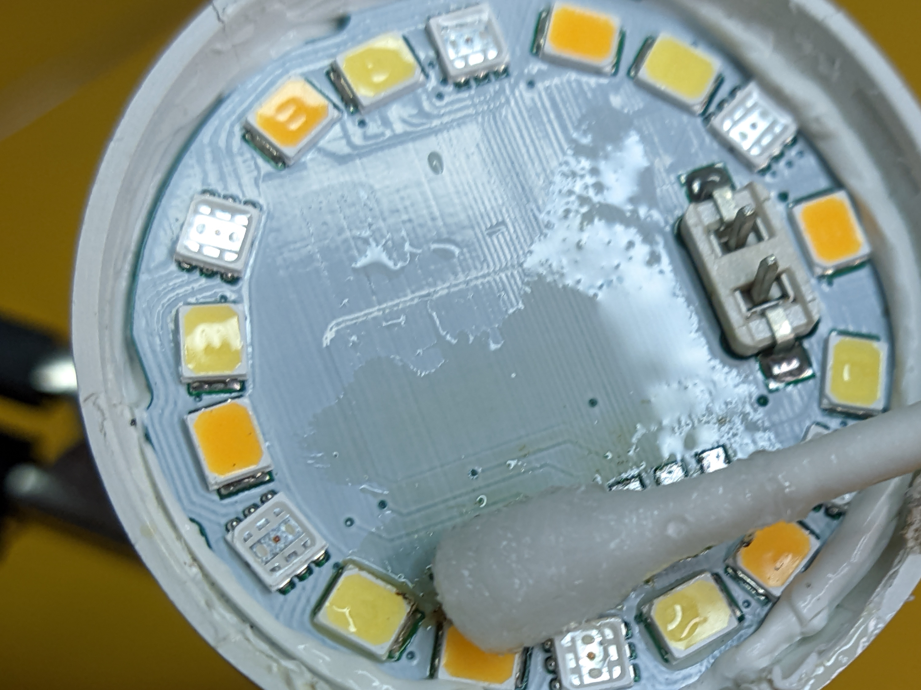
Clean the surface with IPA or other alcohol.
Now is the time to flash the replacement module with firmware you’ll be using.
Put blobs of solder on the pads on the back of the module.
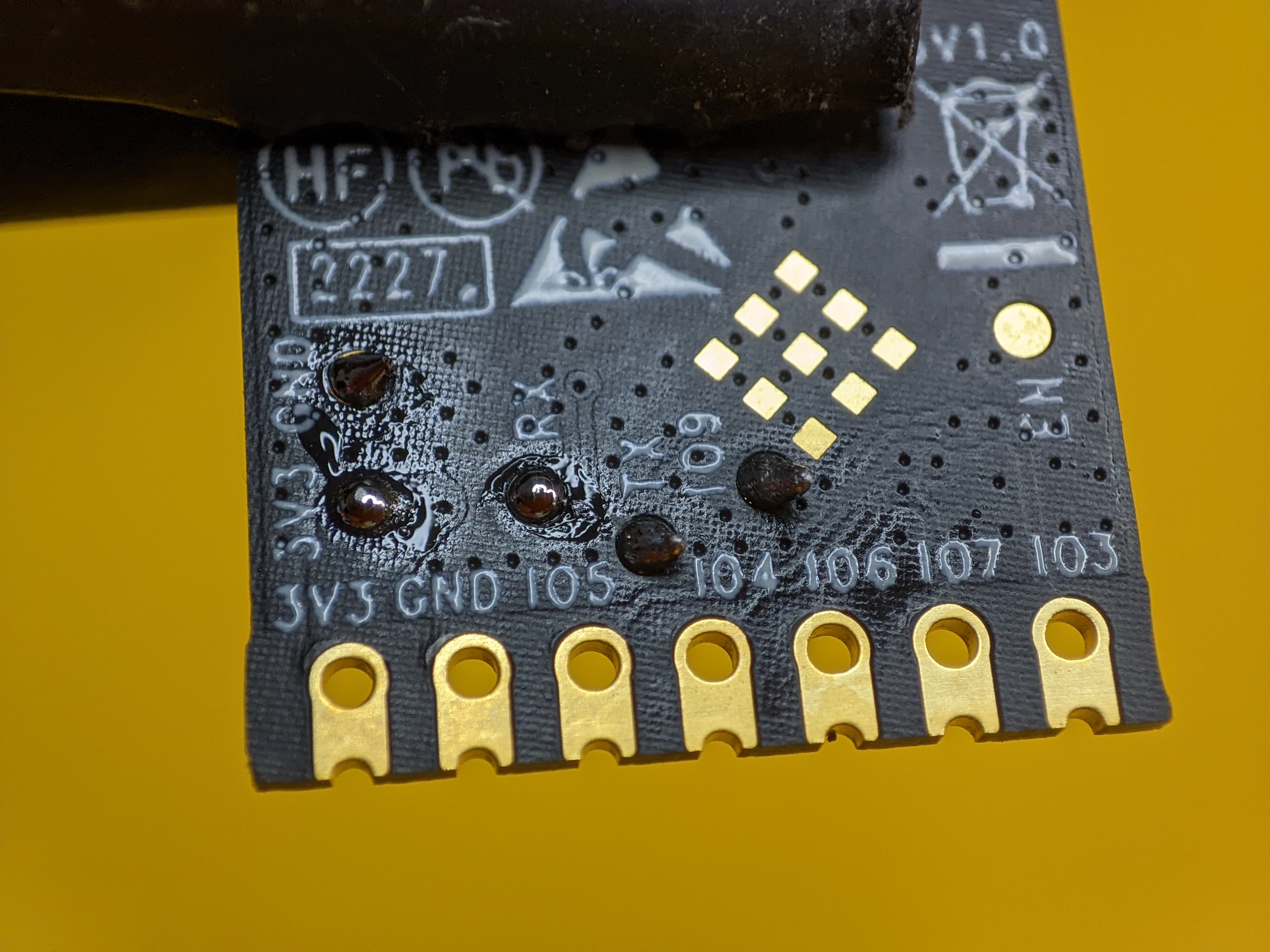
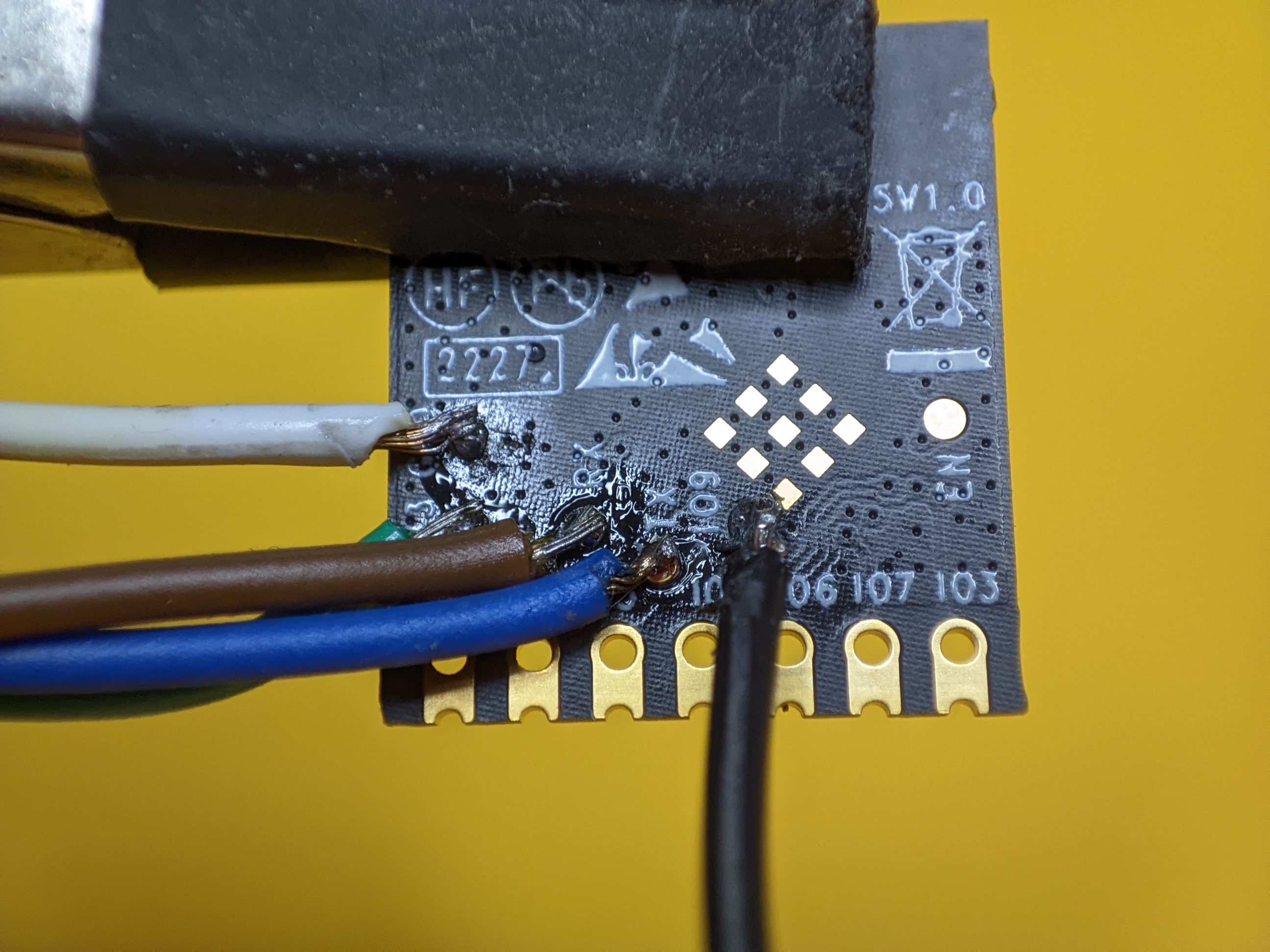
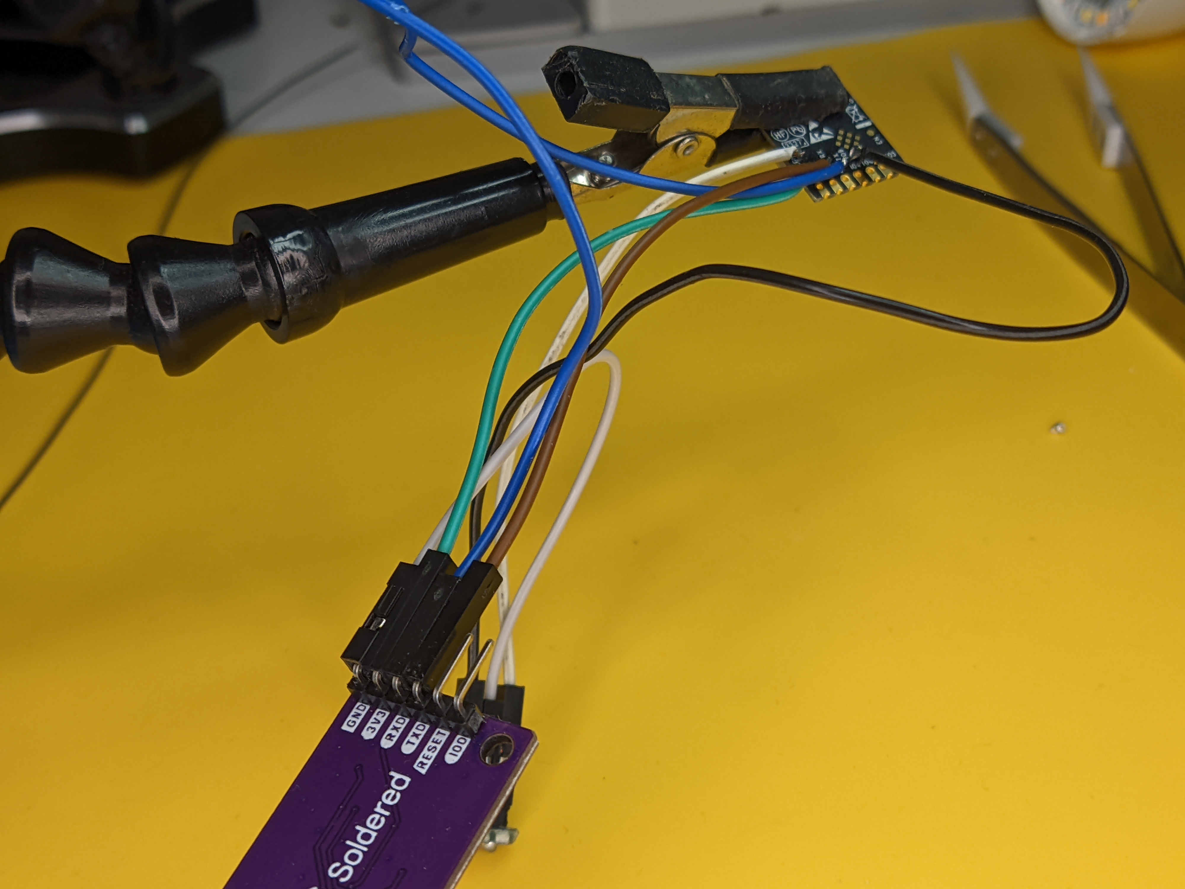
Solder wires that will connect to your USB adapter. You need to solder 3V3, GND, TX, RX, IO9 is optional since it only needs to be grounded during power up. I still solder the wire and keep it connected to ground during the flashing process.
Flash the module with your firmware and make sure it’s working correctly. Don’t forget to unground IO9 to boot the module in normal working mode.
Clean up the solder from the back pads with the solder wick. This is required if the module sits flush with the PCB in the device you’re replacing it.
Align the module with the pads and secure it with tape so it doesn’t move while soldering.
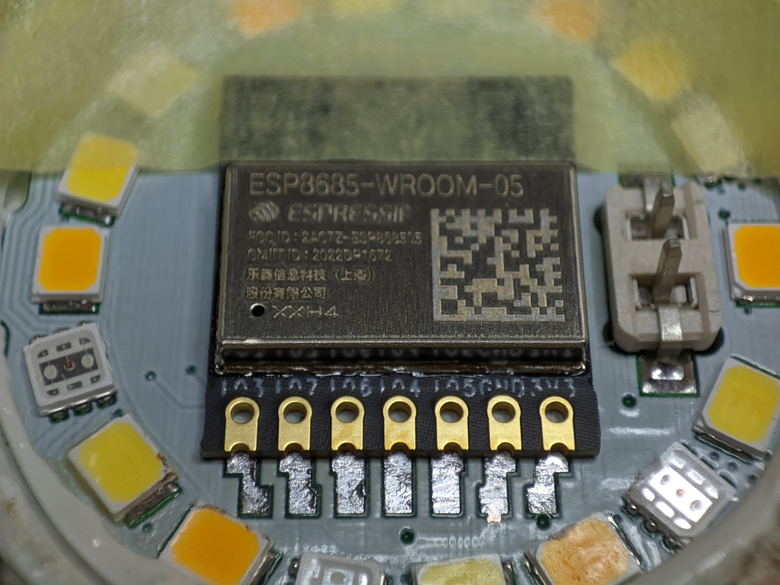
Fill each pad with solder. Make sure your soldering iron is hot enough and use plenty of flux to help the solder flow. You don’t need to make it look pretty, you just need good connections between the module and the PCB pads.
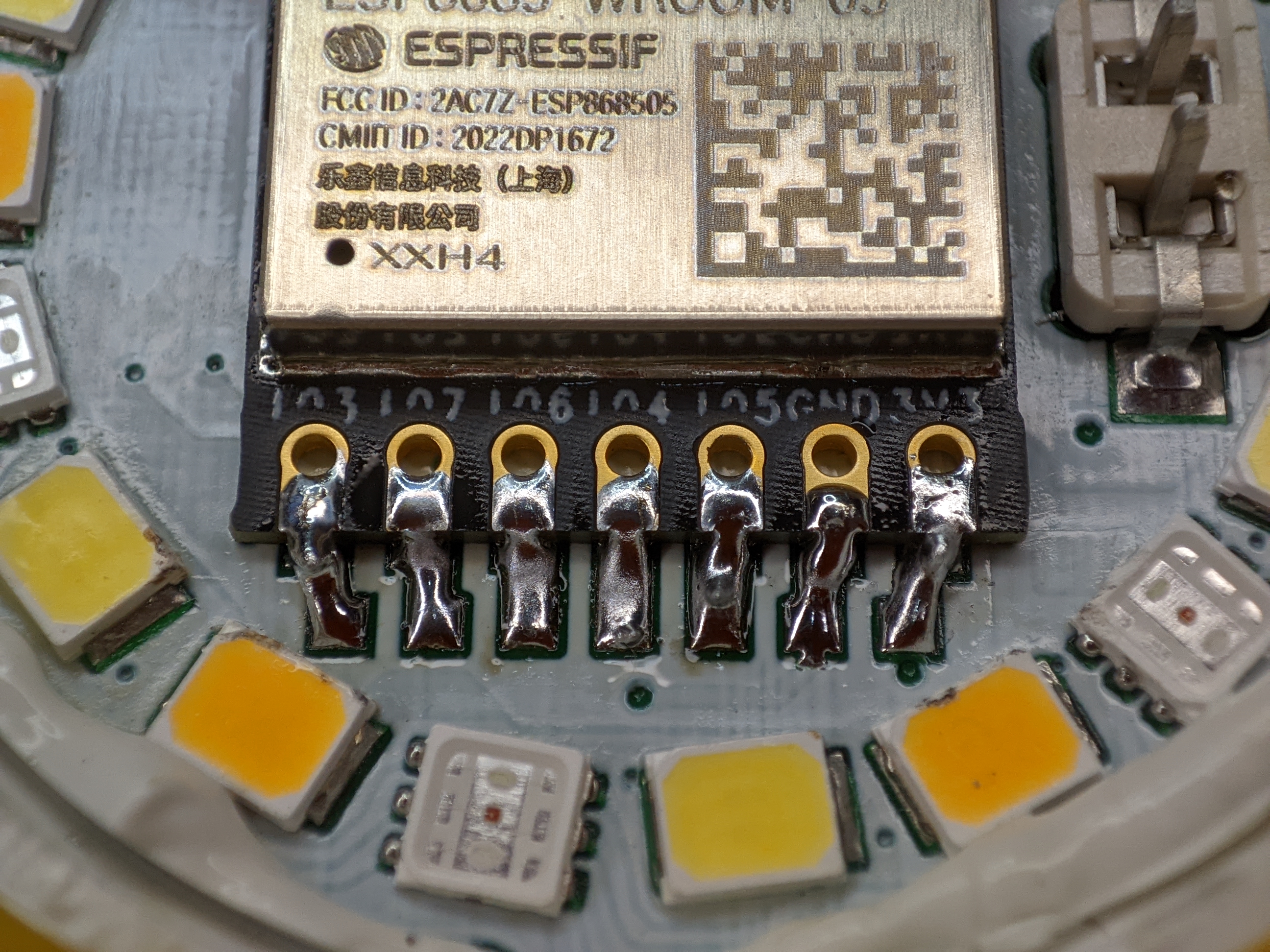
Clean up your work with more IPA and its ready to be reassembled.
Congratulate yourself on a job well done!

Explore more like this
Convert Xiaomi MMC MHO-C401 E-Ink Bluetooth Sensor to Zigbee
Guide on installing Zigbee firmware on the Bluetooth temperature and humidity sensor with e-ink display. The best Zigbee temperature and humidity sensor with an e-ink display is a Bluetooth one....
Kaiweets HT118A Digital Multimeter Review
If you’re into tinkering with electronics one of the tools you can’t go without is a multimeter.
Comments