Custom Firmware on Lanbon L8 LCD Touch Switch
Summary
Great hardware gets great software. Now updated with solderless flashing!
Full disclosure: This is a review sample sent to me free of charge by Safetycorner and Lanbon DE. This article is not influenced by that fact and everything stated is solely my opinion.
Following a series of disappointments with Lanbon’s design and usability philosophy, as described here, it was time for the next step. Disassemble and see if it works with some open source firmware. I even found a GitHub repository with code for Lanbon L8 firmware. Promising indeed…
Disassembly
First, slide the control board off of the relay control part. Still an amazing design feature! There are 4 screws keeping the plate together. After unscrewing them you have access to everything.
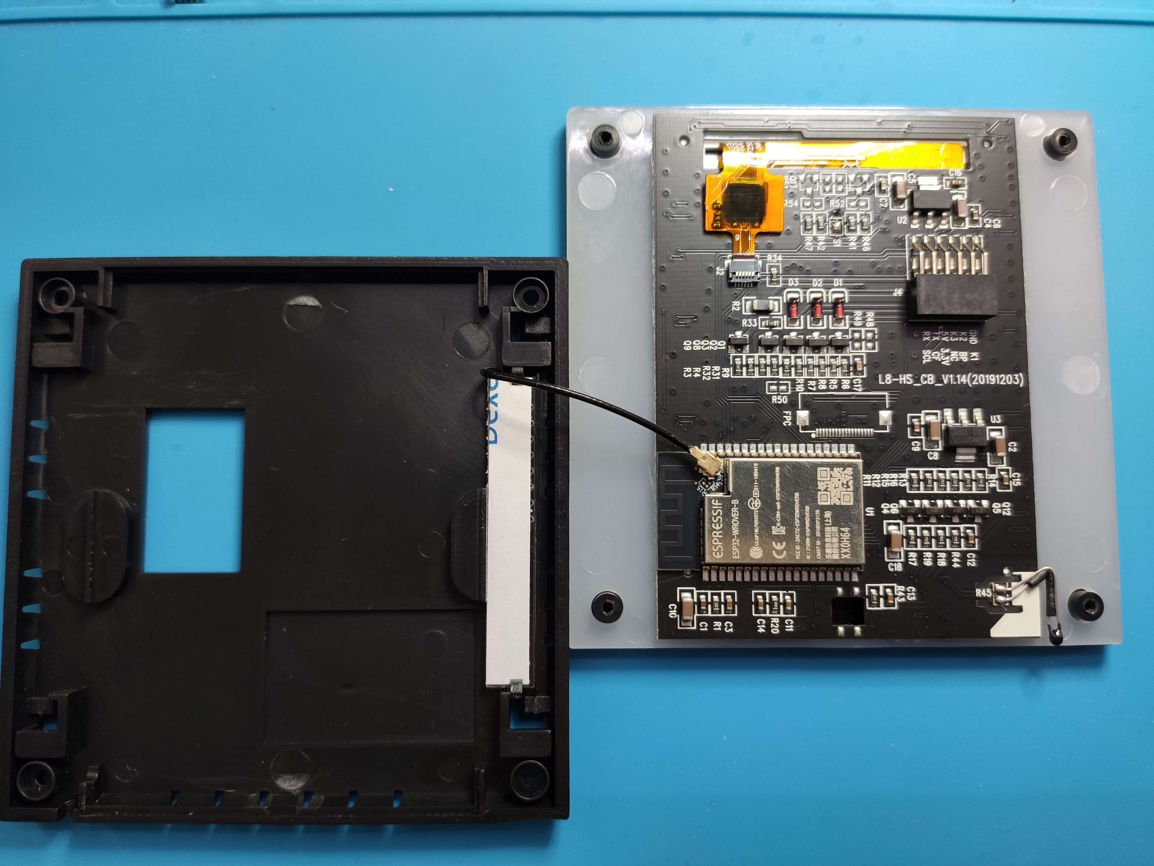
As you can see, it’s powered by the ESP-WROOVER-B Wi-Fi module.
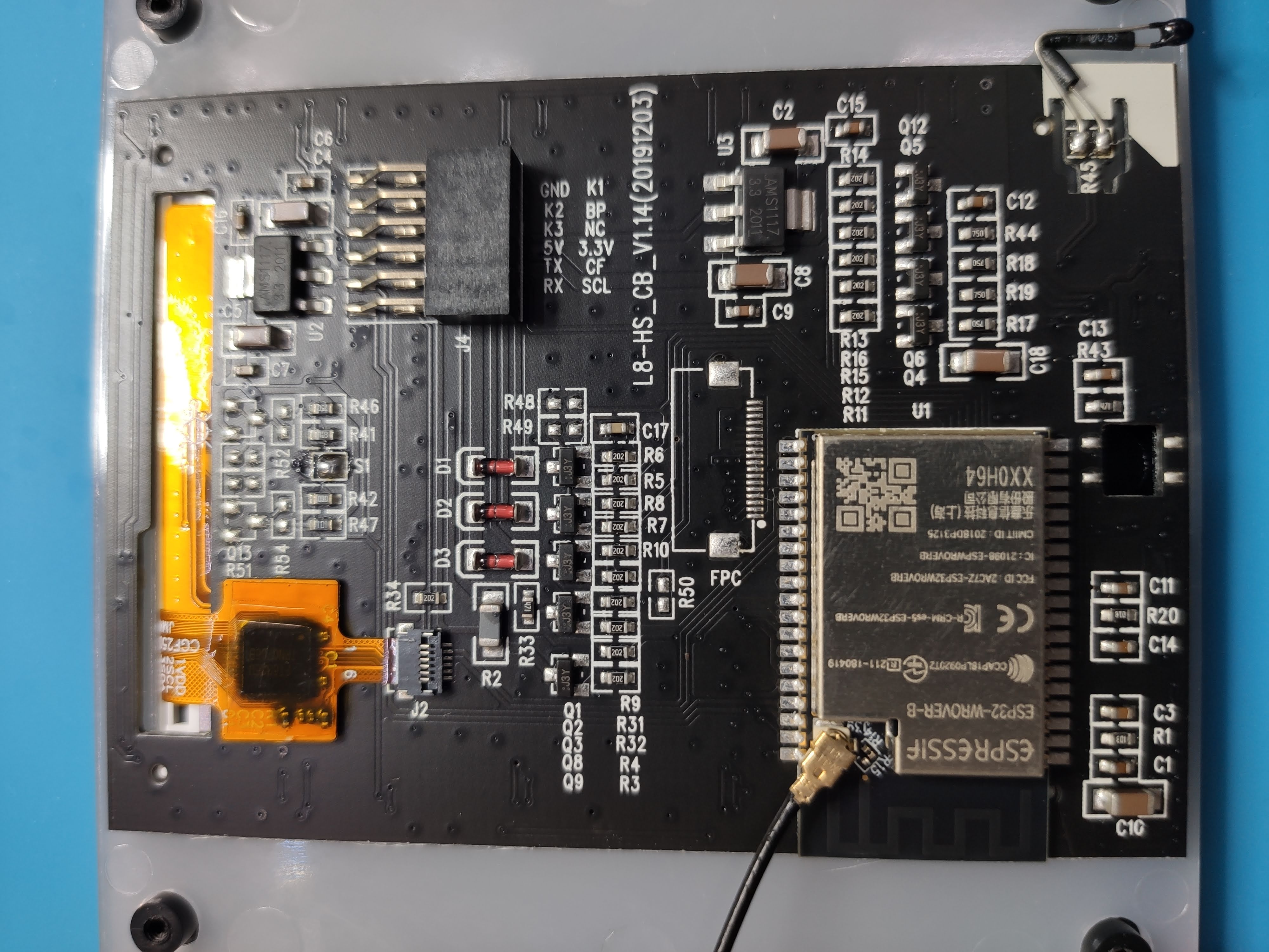
In the top left corner is the I2C FT6336U touch controller connected to GPIO4 (SDA) and GPIO0 (SCL).
Bottom right is the analog temperature probe connected to GPIO39.
The 240x320 LCD screen, driven by the ST7789V controller connects on the other side to the FPC connector visible directly above the ESP32.
Pinout for the screen is:
- Backlight: GPIO5
- CS: GPIO22
- DC: GPIO21
- Reset: GPIO18
- CLS: GPIO19
- MOSI: GPIO23
- MISO: GPIO25
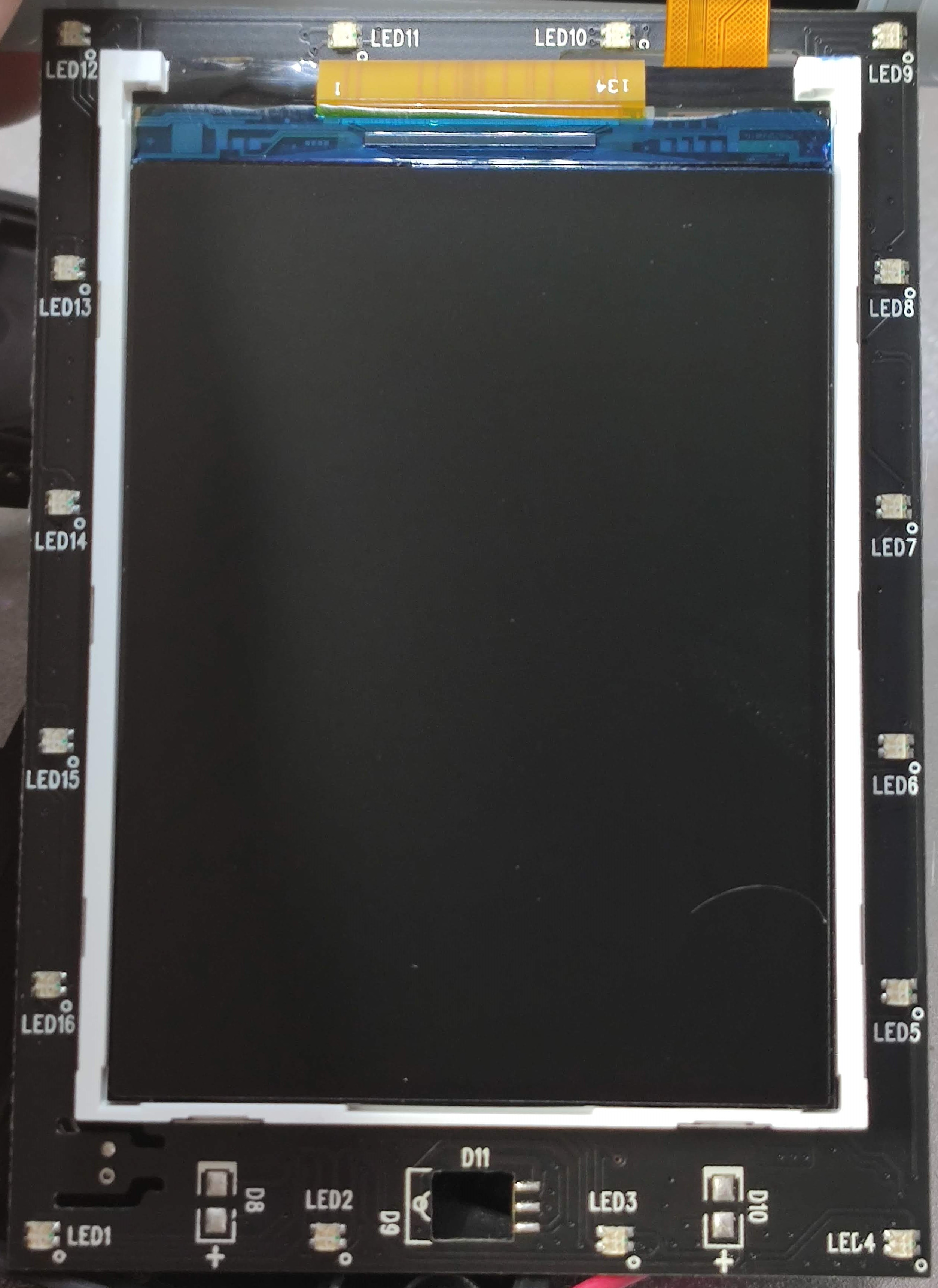
Ambient LED’s are PWM driven on GPIO26 (Red), GPIO32 (Green), GPIO33 (Blue).
Relays are connected from the wall base through the pin header to GPIO12 (Relay1), GPIO24 (Relay2) and GPIO37 (Relay3).
Power monitoring feature uses GPIO32 as Pulse input and GPIO36 as control GPIO.
Solderless Flashing
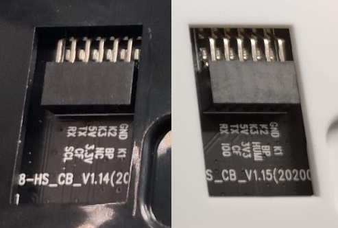
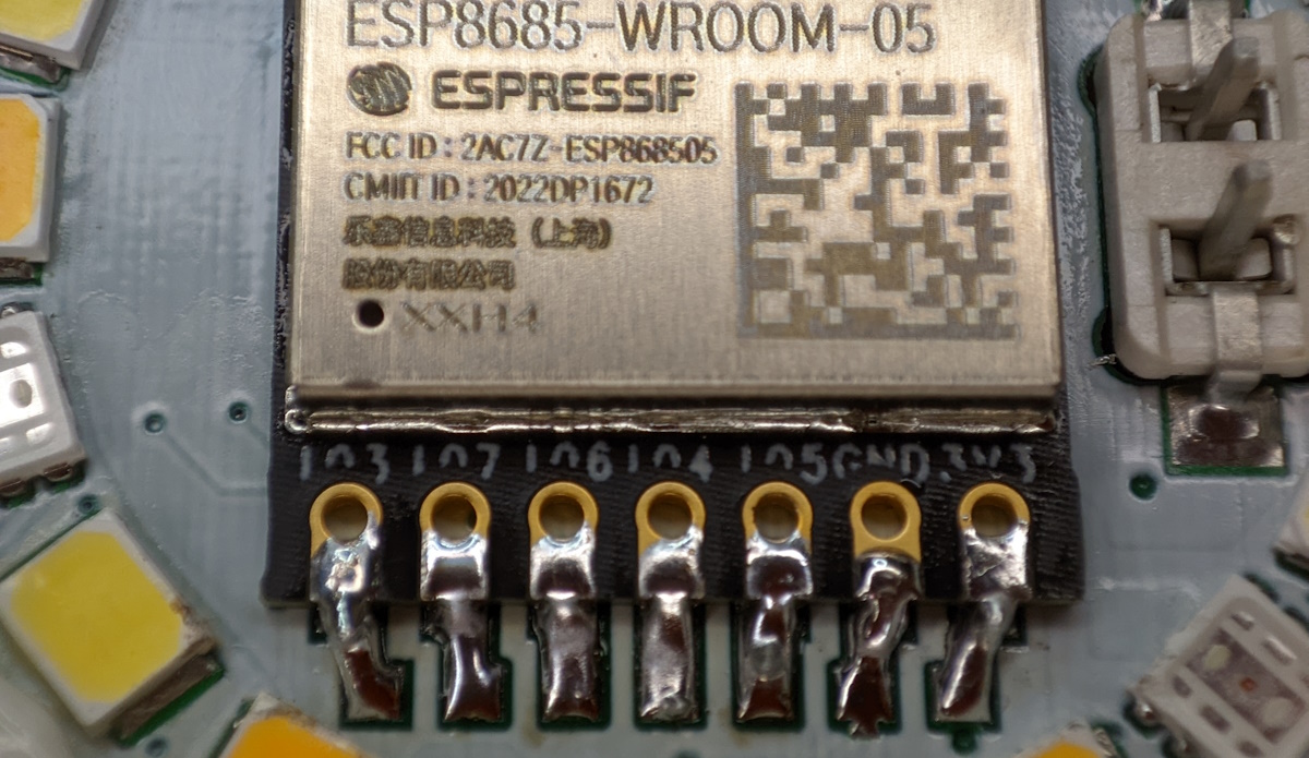
All the pins required for flashing are available on the header that connects the plate to the base. There are differences in labelling between PCB revisions, you will probably receive the 2020 revision which has IO0 correctly labelled
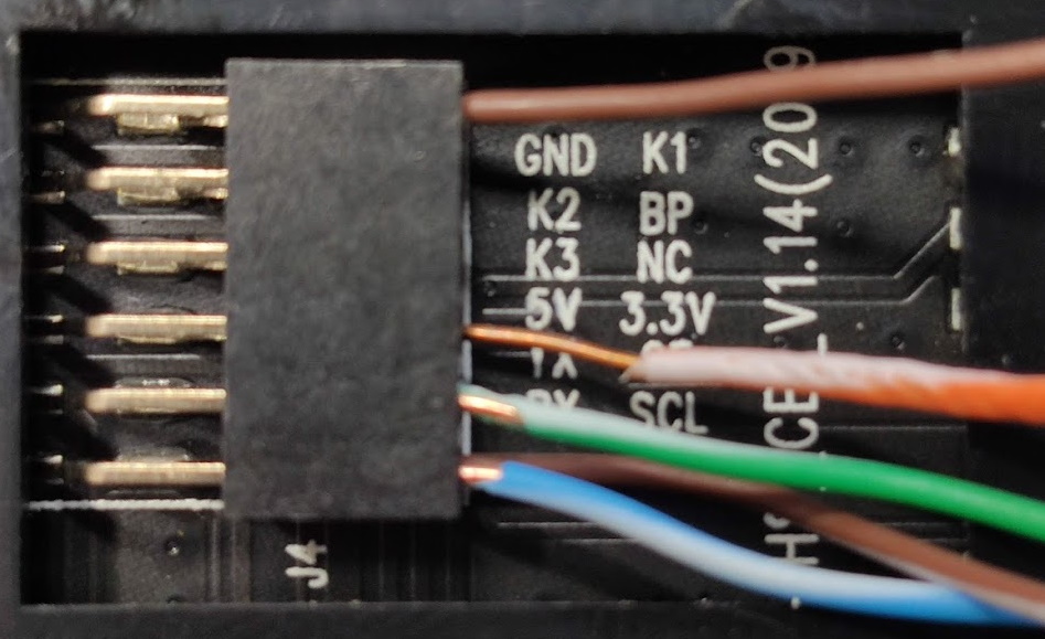
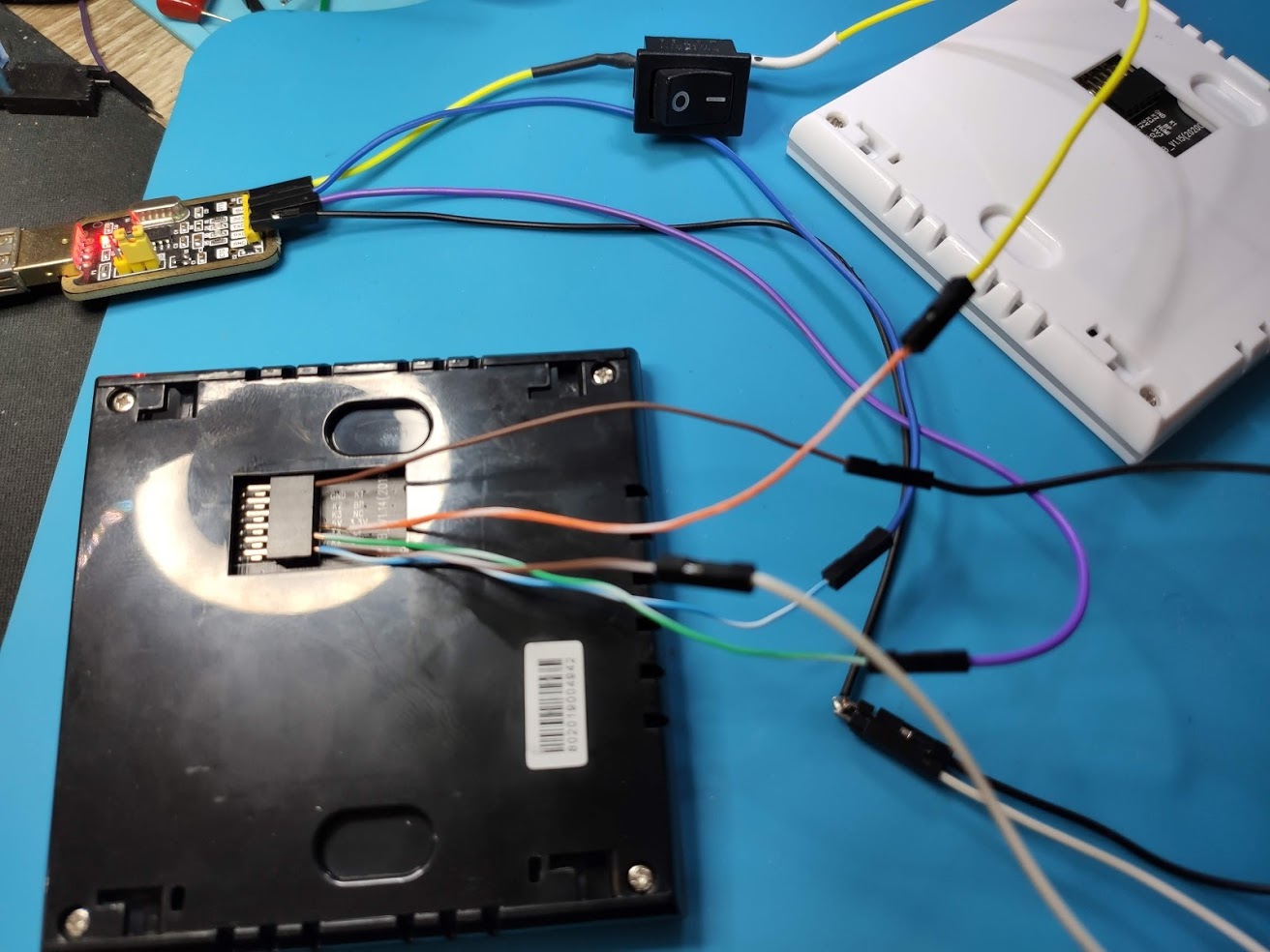
Use thinner solid core wires (f.e. salvaged from Ethernet cables) and insert them in the pin header (Dupont or breadboard wires are too thick).
In the bottom row go IO0 (brown) and 3V3 (orange), top row are RX (blue), TX (green) and GND (brown).
Make sure you have a USB to serial adapter than can provide sufficient power or have a strong and stable source of 3.3v instead. If you don’t have either you can use the 5v pin instead, with power supplied from a 5V phone charger. In this case do not connect power to the USB to serial adapter and have common GND between the three.
You can always solder directly to the ESP32 module if you’re inclined
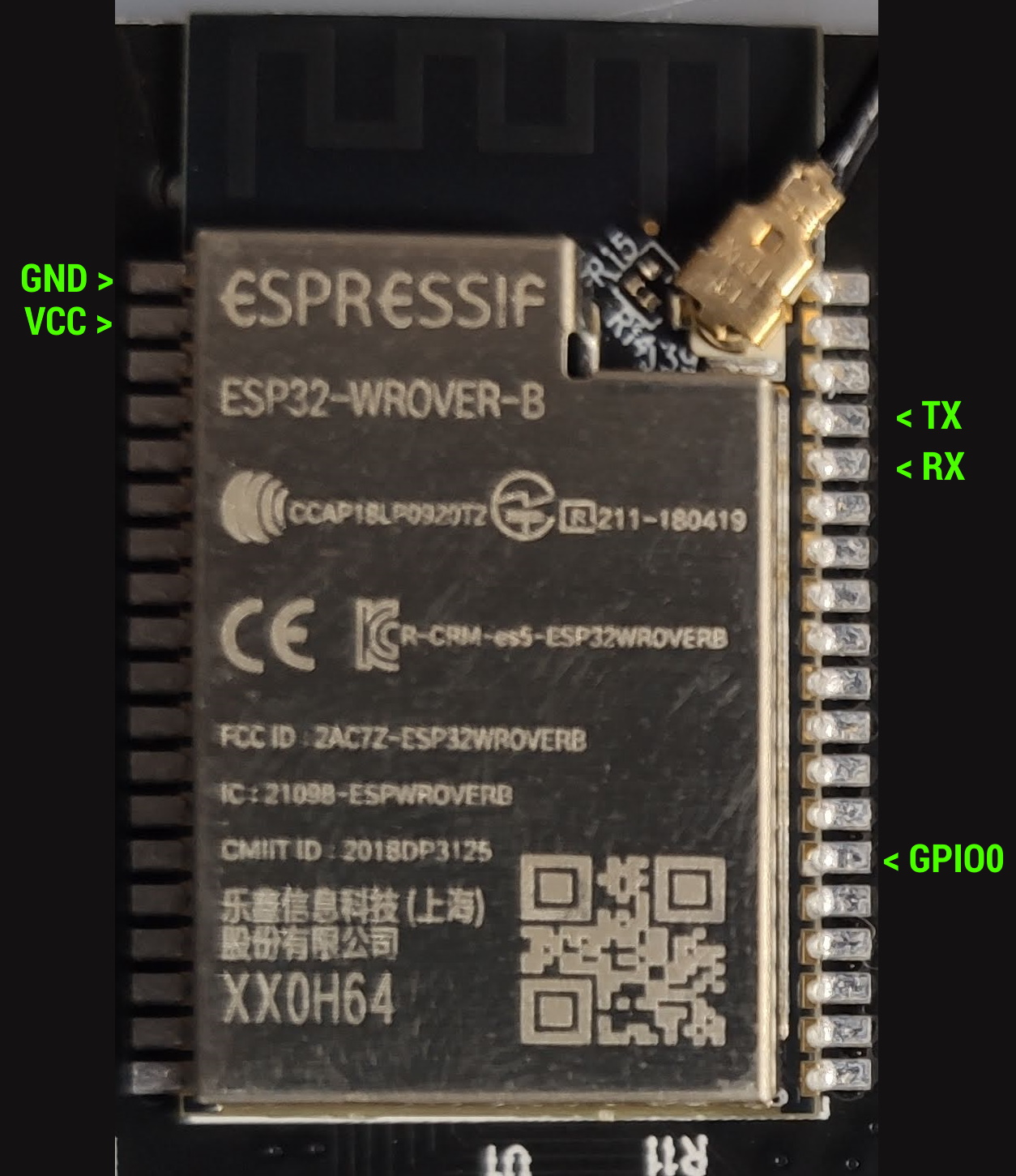
Make sure GPIO0 is grounded during boot/power up.
Tasmota
First and foremost, you need to build a binary that supports the screen and touch drivers. Support for Lanbon L8 in Tasmota has been added recently and you will need to build from the latest development release of Tasmota.
Use PlatformIO and these defines in user_config_override.h:
#define USE_I2C
#define USE_DISPLAY
#define USE_SPI
#define USE_DISPLAY_ST7789
#define USE_TOUCH_BUTTONS
#define USE_FT5206
#undef USE_RULES
#define USE_SCRIPT
#define MAXBUTTONS 16
#define USE_LANBON_L8
Build using tasmota32 environment. You can already use PlatformIO to flash to ESP32 or esptool.py. If using esptool.py you need all the necessary files and this set of options:
esptool.py --chip esp32 --port <your-port> --baud 921600 --before default_reset --after hard_reset write_flash -z --flash_mode dout --flash_freq 40m --flash_size detect 0x1000 bootloader_dout_40m.bin 0x8000 partitions.bin 0xe000 boot_app0.bin 0x10000 tasmota32.bin
After flashing Tasmota, apply the template
{"NAME":"Lanbon L8","GPIO":[0,0,0,0,0,992,0,0,224,0,225,0,0,0,1024,896,0,6624,6592,864,0,832,416,226,0,0,0,0,417,418,0,352,0,0,0,4736],"FLAG":0,"BASE":1}
And configure the screen:
Backlog DisplayModel 12; DisplayRotate 0; DisplayWidth 240; DisplayHeight 320; DisplayFont 1; DisplayMode 0
After all the configuration is done you will be staring at a blank screen.
Open web UI and go to Edit Script menu where you need to paste this script
>D
>B
dt [B1x50y10f2]Lanbon L8
dt [b0:20:60:200:60:10:16:1:3:Relay 1:]
dt [b1:20:140:200:60:10:16:1:3:Relay 2:]
dt [b2:20:220:200:60:10:16:1:3:Relay 3:]
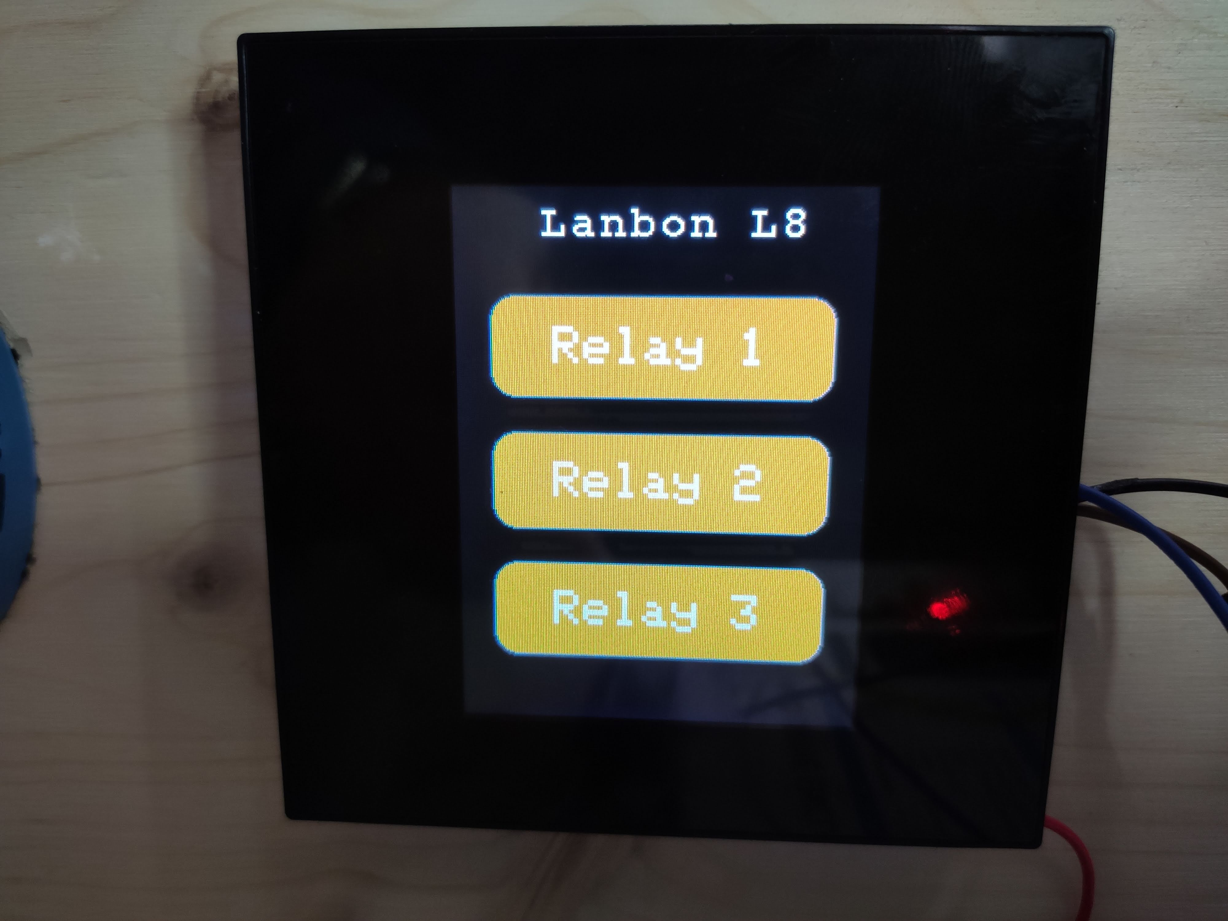
Check the activate box and save settings.
This script will give you three basic touch buttons that are linked to the relay. You can change the labels and colors used in the script. See Tasmota displays documentation on which parameters to use.
Features
With Tasmota you have a working touch screen and its backlight, relays are controllable and ambient LEDs behave as any RGB light in Tasmota. Analog temperature measurements are too high which needs some tweaking.
Power monitoring is not working and is currently implemented as a simple pulse counter.
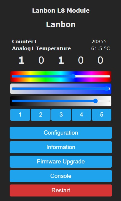
Great! Most of the features are working fine but the UI isn’t really much of an improvement and it is behaving a bit sluggish. Not a clear victory, but an improvement, at least now all the entities are discovered in Tasmota Home Assistant integration and work as they should.
HASP - Open Hardware Edition
Shortly after publishing the review of Lanbon L8 I was contacted by fvanroie through Discord. He wanted me to look at his project built for LCD touch screens running on ESP8266 and ESP32: openHASP.
Inspired by HA SwitchPlate but ported to work on most of the freely available touch screens and based on LVGL graphics library. It uses MQTT to send or receive commands.
Installing
After some trials and tribulations with platformio compiling, pin definitions and screen color inversion issues, with the help from fvanroie and his quick code additions, Lanbon L8 was working with openHASP.
Currently Lanbon L8 is included in openHASP build environments and will be available as a release binary.
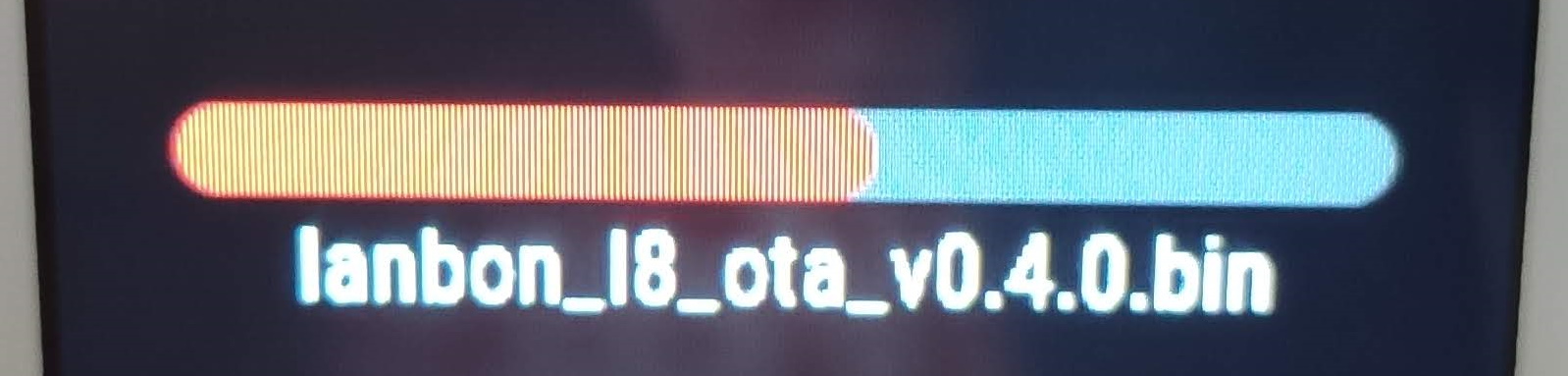
You can flash it with ESP Flasher, just select the port and binary then click Flash and wait.
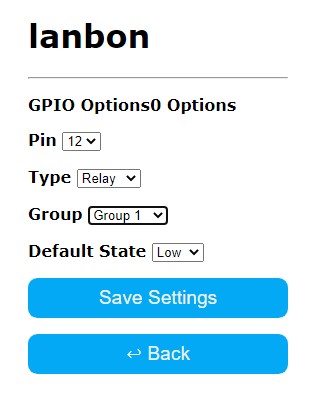
After flashing find its IP address and configure Wi-Fi, MQTT and all GPIOs in the UI:
Compiling
To compile in PlatformIO, clone the openHASP repo, rename platformio_override-template.ini to platformio_override.ini then uncomment:
line 9
	; Uncomment or edit the lines to show more User Setups in the PIO sidebar
    user_setups/esp32/*.ini
    ; user_setups/esp8266/*.ini
and line 30
    ; esp32dev-ili9488
    lanbon_l8
    ; wt32-sc01
You can flash the device from PlatformIO or with esptool.py. If using esptool.py you need all the necessary files created in build_output\firmware folder (boot_app0.bin, bootloader_dio_40m.bin, partitions.bin and lanbon_l8_[version].bin)
esptool.py --port <your port> --baud 921600 --before default_reset --after hard_reset write_flash --flash_mode dio --flash_freq 40m --flash_size detect 0x1000 bootloader_dio_40m.bin 0x8000 partitions.bin 0xe000 boot_app0.bin 0x10000 lanbon_l8_<version>.bin
After flashing, use the QR code on the screen to configure Wi-Fi settings then configure MQTT which is necessary for openHASP to operate.
Touch Screen
New firmware starts with an empty screen. You need to draw objects in their pages, either by sending jsonl lines or uploading a jsonl file. Every step is described in hasp documentation.
openHASP is powerful and highly customisable and offers many different possibilities. Here are some rough examples of possible designs:
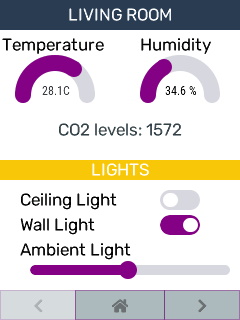
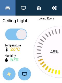
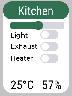
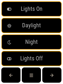
Configuration .jsonl for some of the examples can be found in hasp documentation.
UI is incredibly snappy, redraws very fast and ESP32 supports up to 12 screens. That’s way better than the original firmware or Tasmota.
One caveat is that you need a home automation system that will handle all the logic and update or redraw the objects. That some extra work, amount depending on the platform you use, but ultimately it pays off since you get a highly customisable and beautiful touch UI to display almost anything you’d want to in a way you want to.
Other Features
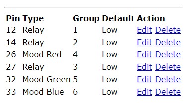
Relays and LEDs are configured using Configuration - GPIO Settings. Assign each GPIO to its group. openHASP controls groups not individual GPIOs. That is by design since you can assign a screen object to a group.
Each group can be controlled using command output[x] where x is the group number. To turn on relay #2 which is configured into group #2 send payload 1 to MQTT topic hasp/lanbon/command/output2 (lanbon is the configured topic name for the device)
You can use this command to configure all GPIO’s at once
config/gpio {"config":[2360346,2491680,2623009,2097420,2097678,2097947,0,0]}
When using MQTT send to topic hasp/<nodename>/config/gpio
esphome
Esphome has a driver for the ST7789V screen but the resolution is currently fixed and too small for the screen. Naturally, relays and LEDs work but there is no support for the touch screen so I didn’t proceed any further.
Final Verdict
You can order black or white version from AliExpress, Amazon.com or Amazon.de!
It is good to know there are better options than what originally came with the switch. You can choose between the incredible customizability of openHASP, tight integration of Tasmota with more basic UI and I believe that esphome will catch up easily if there’s interest.
All three are open source and free making the final verdict solely yours!

Explore more like this
Replace Tuya CB2L, WB2L, BW2L Modules with ESP
Replace Tuya TYWE2L, CB2L, WB2L, WR2L, WBR2L, BW2L and similar Wi-Fi modules with an Espressif ESP32 or ESP8266 light module.

Comments