Frankenstein Saturday 2: Electric Roller Shade Boogaloo
Summary
How to replace a Realtek WR4 module with an ESP8266 running Tasmota.
In the previous article about Zemismart ZM25TQ roller shades motor I hinted at installing Tasmota despite it having a Realtek Wi-Fi module which is not compatible with Tuya-Convert or Tasmota. While replacing the module itself is quite trivial, working with this motor requires extra tools, some experience and patience.
Disassembly
Lets open it up!
But no, let’s try and keep at least 99% of it intact. First you need to remove the end cap where the cabling is by unscrewing the two screws and pulling it out. From the opposite side you need to remove the safety pin with push pin pliers. Next locate three metallic dots on the tube. Those are small pins holding the motor in place, you have to push them in to free the end cap and motor casing from the tube.
remove the white plastic cap. You will need to use a prying tool and be persistent, it will pop out. Next get a long tool and push the innards from the white cap end towards the cabling end until you have everything pop out of the tube. Do not try to pull everything out by grabbing the all the wires like I did initially. Store all the motor gears and bits and pieces in a safe place.
How does it work?
Once we have it out its time to examine what is inside. We can see a motor with a PCB, that’s the control PCB. Next to it is the power supply secured in heat shrink tubing. We can see the “Set motor” button has a red and black wire connected to the control PCB. The white wire connects the RF receiver wrapped in heat shrink to the JST connector on the control PCB. Grey wire is an IPX Wi-Fi antenna connected to WR4.
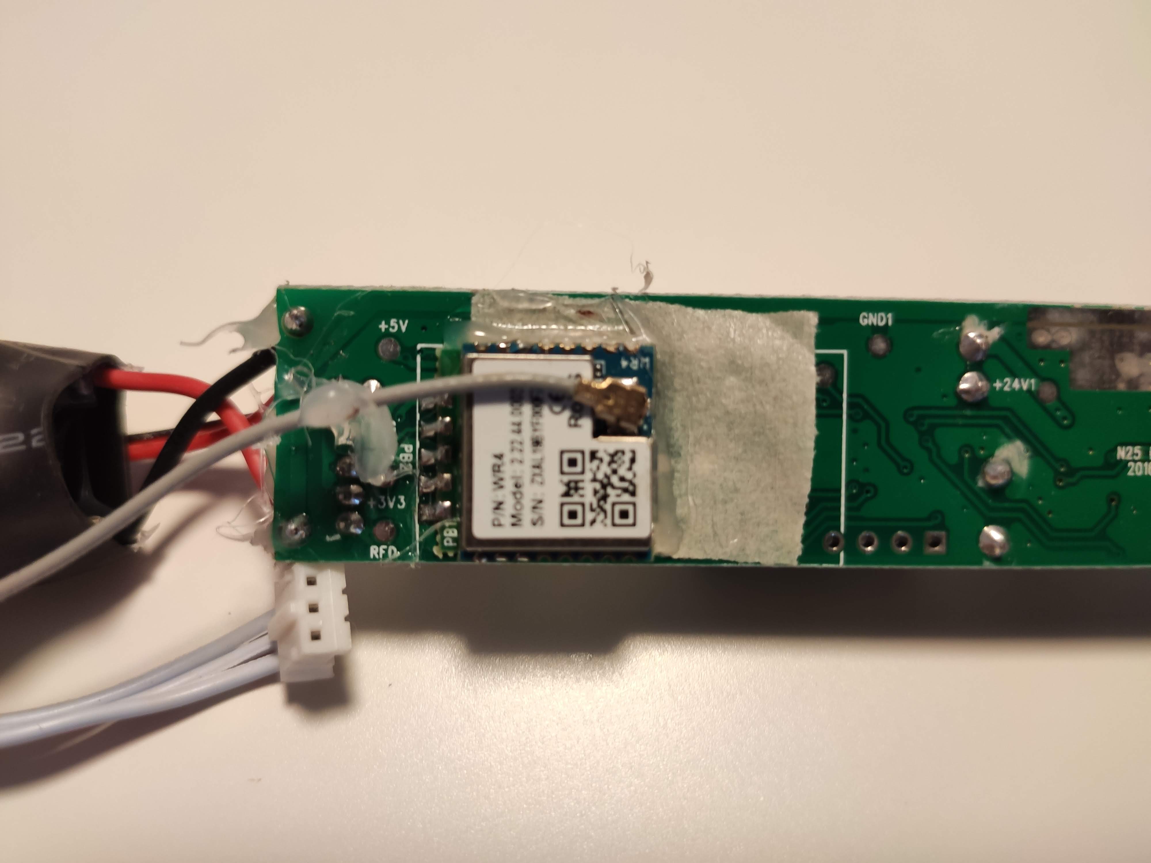
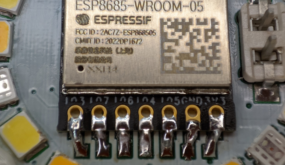
The control PCB carries the Realtek WR4 module. On the other side the main control MCU hides under the two capacitors. It is marked SK6T6C and a short google search later we know its STM8S003F3. We can see 24V, 5V and 3.3V markings on the PCB. That means there’s different voltages running around and we have to be careful not to accidentally connect things to wrong voltage. 24V being the biggest number also tells us that the PSU is probably 24V and that the motor runs on 24V as well. Checking STM85003F3 datasheet shows its operating on 5V and WR4 is on 3.3V.
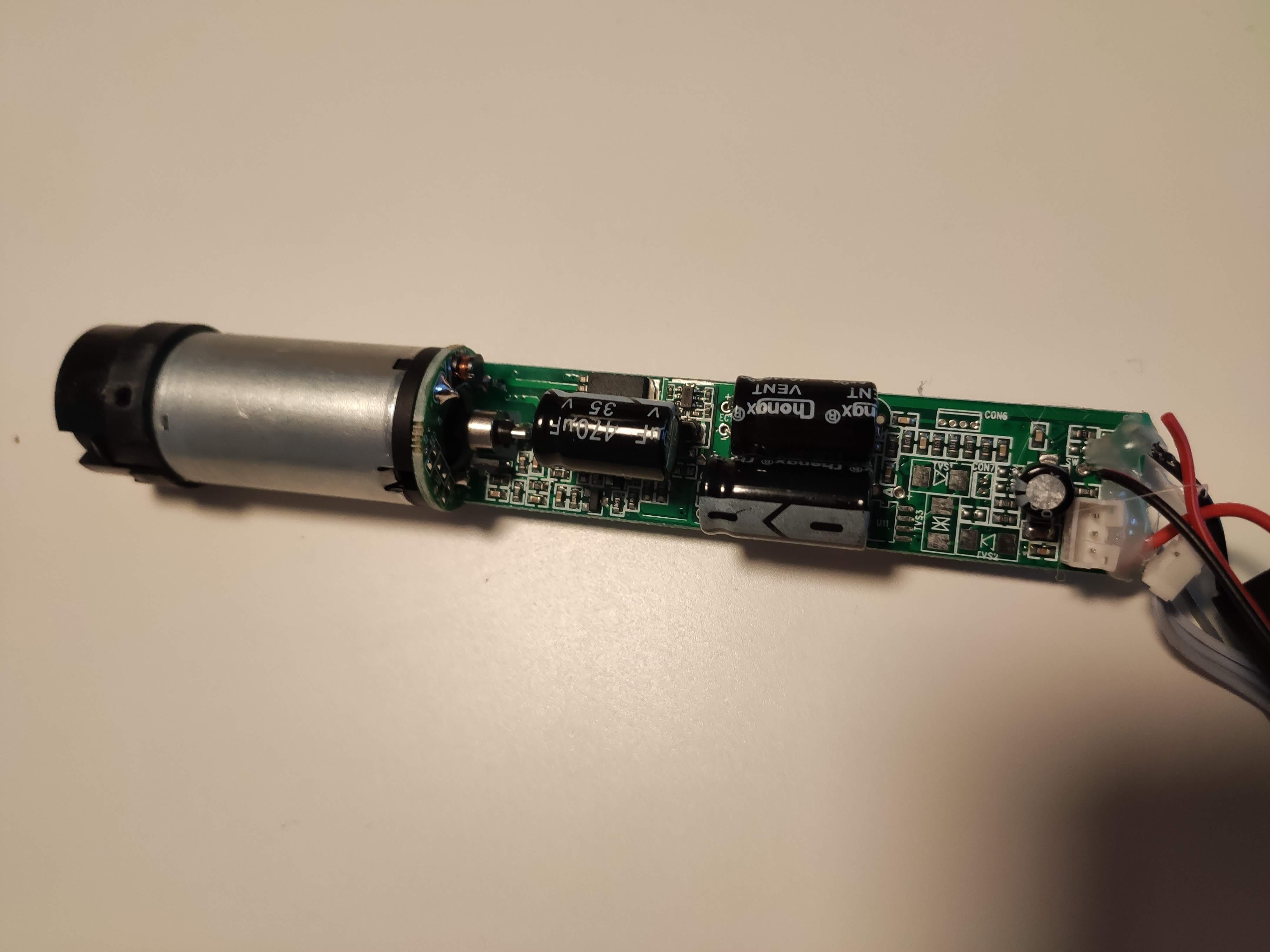
Notice the separated red wire. That happened when I was trying to pull everything out by grabbing all the wires, don’t be like me and simply push from the motor side. Also, this is not the only thing I managed to break.
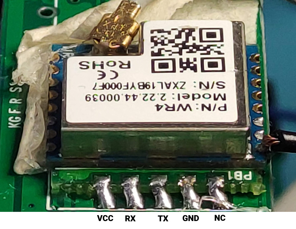
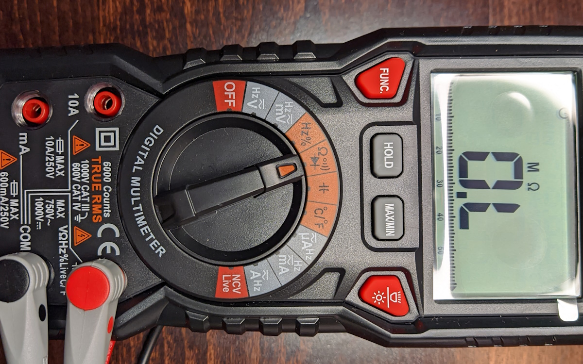
I took some time tracing and checking connections with a multimeter and WR4 and MCU datasheets. I discovered the WR4 module has only four pins with continuity, the RF receiver and the motor button are connected to the MCU. That implies the Wi-Fi module is there only to transmit MCU statuses and send commands to the MCU.
How does it communicate?
Now that the pinout is known I can try and hook up a CH340G serial-to-USB adapter and see if I get any serial traffic using RealTerm set to serial baudrate 9600 which is the default Tuya baudrate. Good news, I can see some serial messages starting with 55AA which means default Tuya protocol is used.
For the next phase of examination I took a NodeMCU flashed with Tasmota and module set to TuyaMCU (54). Hooked up TX to WR4 TX, RX to WR4 RX, 3.3v to WR4 VCC and GND to GND and powered everything using the motor power supply (be very careful around the mains part of the power supply!). This is to see if Tasmota will be able to communicate with the MCU.
And yes, when I operate the motor with the remote I can see tuya statuses from the MCU in the webUI of the console, excellent! But, when I try sending serial commands or tuyasend commands, nothing happened. That must mean there’s some issue on the TX pin. I took the MCU datasheet and locate its TX and RX pins which would be connected to the Wi-Fi module RX and TX and checked how are they connected with a multimeter.
That revealed that both RX and TX pins have resistors in line to drop voltage from MCU’s 5v operating voltage. I tried hooking the TX pin using a level shifter but that didn’t work so I simply connected the NodeMCU right before the resistor (ESP8266 is, supposedly, 5v tolerant but there’s still a debate going on on how safe that is). I tried sending my favourite SerialSend5 55aa0001000000 and boom, MCU responds with all dpID statuses (while I did try and decipher what they all do now, that will be covered in another article). Hell yeah, we have first contact!
Bye Realtek!
Now that I’ve confirmed it will work with Tasmota I can remove the offending WR4. This would be easier with a soldering heat gun but it is doable with a cheap soldering iron and some solder wick.
You might notice a solder blob on the second pin from the left. Not gonna lie, I slightly tore off the pad from the PCB during desoldering so that solder blob holds it all together. I connected the NodeMCU again to check if everything works without the WR4 and it does. Excellent!
I took my my favourite module, the ESP-M3 module flashed it with Tasmota and configured the basics in preparation to replace the WR4 and, suddenly, I remembered there was an antenna. Remember the antenna? I need that antenna so the signal isn’t blocked by the metal tube and I don’t have any modules with IPX antenna connectors. Luckily, the internet provides and this excellent guide shows how easy it is to solder an external antenna to the PCB antenna on the module. Secured everything with some hot glue.
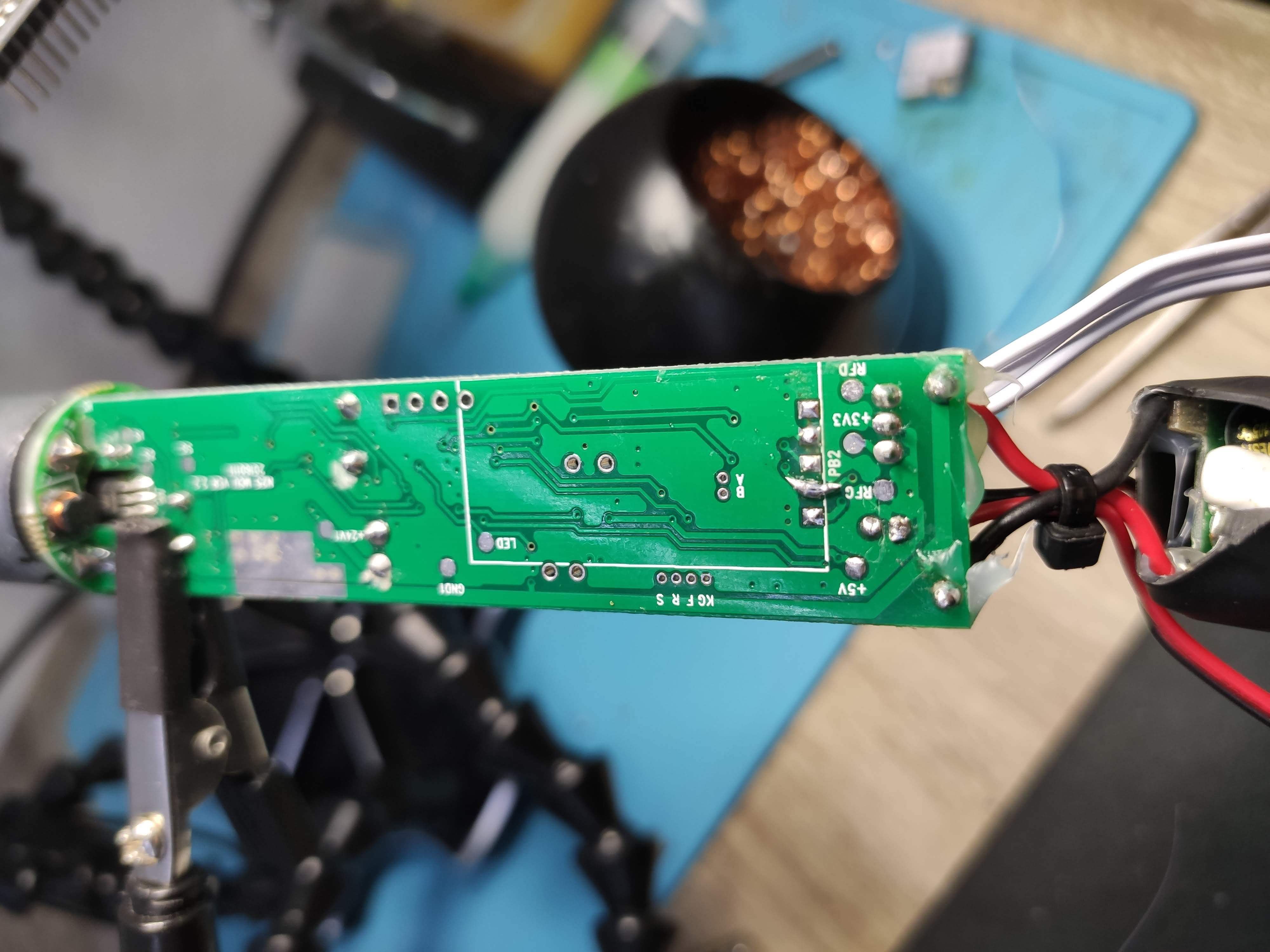
Next I soldered RX, 3v3 and GND pins to the liberated pads. For the TX pin I took a thin wire from a CAT5 cable, routed it to the other side using one of the through holes. Instead of soldering to the resistor I check continuity on the bunch of unpopulated pads and discovered one that is connected to the MCU RX which goes to our module TX pins. I used that pad instead and soldered it all together and I forgot to take a picture of it.
Wrapped everything in electrical tape for safety and security. Plug the motor back in and check if it is all working. I checked the RSSI to verify the antenna is connected properly. Everything checked out, Zemismart ZM25TQ now runs Tasmota.
Assembly
This is the point where everything came crashing down! Everything due to my stupidity, stubbornness and trying to finish everything up at 2am while hopped up on solder fumes.
Remember how we got the motor out? Now, my 2 am brain told me to put it back in using the same process but in reverse. So I put everything in the tube and pushed it in slowly, once it got stuck I took a rod and started pushing as hard as I could on the power supply to push everything in. Not only did the motor not pass the halfway point, the ominous sounds of things breaking filled the room. Uh-oh! After pulling everything out I witnessed my “masterpiece”, cracked PSU PCB, tore the main L wire, ripped one of the button wires together with its pad and tore both wires powering the control PCB. Well F#$%!!!
Assembly Take 2

After a cool down period of a few days I went back in with renewed vigor and a functioning brain. I had a plan:
- fix everything I busted up
- return the motor to the tube without breaking everything again
First the button wire. I found where the pad was connecting to, scraped off the green paint and soldered the wire to the trace and secured it with copious amounts of hot glue. Next the 24v power wires, remove the short mangled ones and replaced them with two two piece wires, again, secured with ungodly amounts of hot glue. I will use a small(ish) wire terminal to connect those. The broken PCB could’ve been an issue but its only a PSU so there’s only the two “+” and “-“ traces which I patched by scraping the PCB until I revealed the traces then soldered them together with a lot of solder. Lastly I soldered back in the mains wires and, yes, heaps of hot glue to secure. I bundled all the antenna and button wires with cable ties for extra security.
Witness the monster! Can’t get more Frankenstein that this.
How did the motor return to its tube? It was actually pretty obvious second time around, just push it in from the motor side. But, to do that I had to cut off the plug and desolder the small button first. After that everything slotted in with relative ease, I just had to pay attention that the pin holes on the tube align with the holes on the motor casing. I used small screws to secure this time in case I need to take it all apart again. Re-soldered the button and didn’t bother with the plug since I will install it to bare wires in the wall anyway. Returned the end caps and security pin and everything was almost the same as when we started.
Plugged everything in to check and its working, Wi-Fi signal is good and motor is spinning. In the next installment we’ll see how to control it in Tasmota and Home Assistant.

Explore more like this
Convert Xiaomi MMC MHO-C401 E-Ink Bluetooth Sensor to Zigbee
Guide on installing Zigbee firmware on the Bluetooth temperature and humidity sensor with e-ink display. The best Zigbee temperature and humidity sensor with an e-ink display is a Bluetooth one....
Kaiweets HT118A Digital Multimeter Review
If you’re into tinkering with electronics one of the tools you can’t go without is a multimeter.
Comments